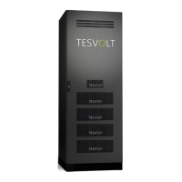
Ts 48 V bATTeRy sTORAge sysTeM 17
© TESVOLT We reser ve the right to make technical changes. Version RD.TI.015.E.ENG_Installation_Manual_TS48V_v.C.01 Last revised 06/2020
. SCOPE OF DELIVERY FOR STORAGE SYSTEM COMPONENTS
ITEM QUANTITY* DESCRIPTION
TS 25 TS 40 TS 50
1
1 1 1 APU LV
2
5 8 10 Battery module 4.8-1C-LV48 incl. Active Battery Optimizer (ABO)
3
1 1 1 APU LV connector kit from the APU to the 1st battery module
3.1
1 1 1
L
LV S-shaped connector
3.2
1 1 1
L
Short LV I-shaped connector
3.3
1 1 1
L
Rack balancing bridge
3.4
1 1 1
L
CAT 6 patch cable – 0.27 m ribbon
3.5
4 4 4
L
DIN 6923 - M8 self-locking flanged nut
3.6
2 2 2
L
DIN 6921 - M8 x 16 hexagon flanged bolt
4
4 7 9 LV module connector kit
4.1
8 14 18
L
Long LV I-shaped connector
4.2
8 14 18
L
DIN 6921 - M8 x 20 hexagon flanged bolt
4.3
4 7 9
L
CAT 6 patch cable – 0.27 m ribbon
4.4
4 7 9
L
Rack balancing bridge
5
1 1 1 LV DC connecting cable set
5.1
1 1 1
L
DC connecting cable – 5.00 m 120 mm
2
(+, with red marking on one end, M8 ring cable lug)
5.2
1 1 1
L
DC connecting cable – 5.00 m 120 mm
2
(-, with blue marking on one end, M8 ring cable lug)
5.3
1 1 1
L
CAT 6 patch cable – 5.00 m
5.4
1 1 1
L
Grounding cable
–
5.00 m 16 mm
2
(M8 ring cable lug on one end)
5.5
1 1 1
L
Red heat shrink tubing – 65 mm for 120 mm²
5.6
1 1 1
L
Blue heat shrink tubing – 65 mm for 120 mm²
5.7
2 2 2
L
M8 ring cable lug for 120 mm²
6
2 2 2 Type plate TS 48 V
7
1 1 1 TESVOLT TS 48 V Installation and Operating Manual
8
1 1 1 TESVOLT USB-Stick
9
1 1 1 Battery room sticker
* The quantities given are for the standard configurations of the storage unit models. The quantities provided here will vary accordingly in non-
standard configurations.