INsTAllATION 35
© TESVOLT We reser ve the right to make technical changes. Version RD.TI.015.E.ENG_Installation_Manual_TS48V_v.C.01 Last revised 06/2020
22
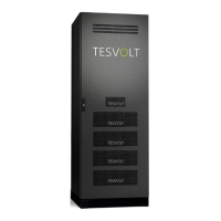
Only connect the DC cables
5.1
/
5.2
to the APU LV once the
SMA Sunny Island is completely connected. Fasten the DC con-
necting cable with red marking
5.1
to the CHARGER “+” connec-
tion
1
and the DC connecting cable with blue marking
5.2
to the
CHARGER “–” connection
2
. Use two M8 self-locking nuts
3.5
to
fasten, and tighten to a torque of 12 Nm.
Finally, fix the DC cables in the cable retention clips
F
.
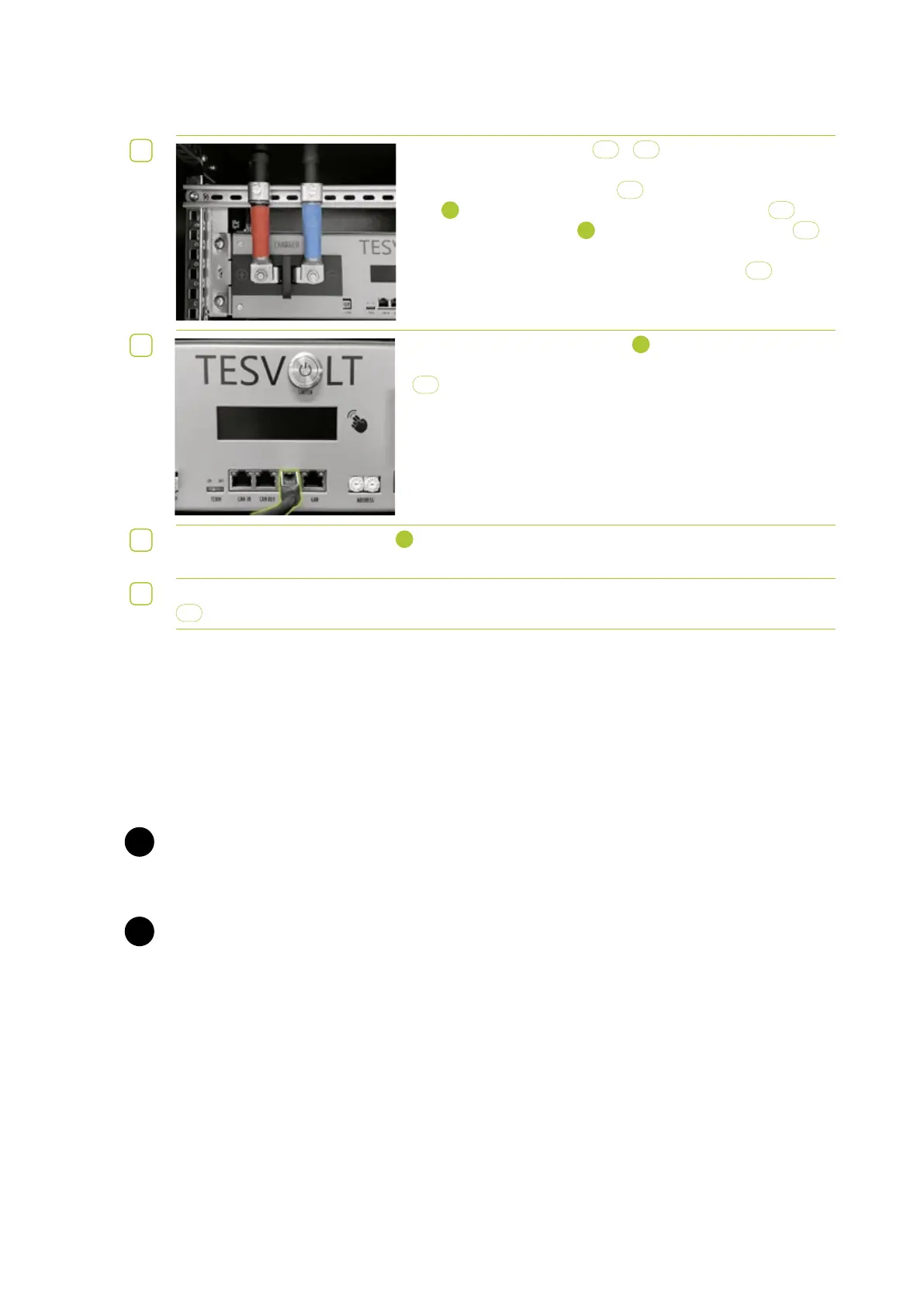
23
Connect the CAN SMA connection
7
on the APU LV to the Com-
Sync IN connection on the SMA Sunny Island using a patch cable
5.3
.
24
Then connect the LAN connection
8
on the APU LV and the ComETH connection on the
SMA Sunny Island using the switch.
25
Finally, fill out the commissioning protocol. You will find a template for this on the TESVOLT USB-Stick
8
.
. ESTOP CONTACT
The TS 48 V has a quick shutdown (e-stop) function. The unit has a Wago 734-162 two-pin plug that is
accessible from the outside for this purpose. This electrical connection can be connected to an external
control system using the matching Wago 734-102 socket. If necessary, the external control system can
switch off the unit as quickly as possible using a separate (i.e. completely independent) switching path.
The shutdown is much faster than the normal shutdown process. The wiring connection may only be
implemented using a floating contact.
WARNING! Possible damage to the unit due to use of the e-stop.
The e-stop contact is used to quickly shut down the system. As the battery storage system is not
switched off properly when the e-stop is used, damage to the TS 48 V can occur. For this reason, never
use the e-stop to switch off the unit under normal circumstances.
WARNING! Possible damage to the APU or external components due to an unsuitable switching
device.
Connecting a non-floating switching device can result in damage to the APU and/or external compo-
nents.
E-stop states
1. Contacts 1 and 2 of the Wago plug are connected, e.g. by an external relay; the e-stop is inactive
and the APU LV is thus switched on.
2. Contacts 1 and 2 on the Wago plug are open, e.g. after activation of the external switch; the e-stop
is active (this is shown on the APU LV display); the DC connection between the TS 48 V and the
SMA Sunny Island is interrupted.
STOP
STOP