20 Ts 48 V bATTeRy sTORAge sysTeM
© TESVOLT We reser ve the right to make technical changes. Version RD.TI.015.E.ENG_Installation_Manual_TS48V_v.C.01 Last revised 06/2020
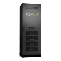
. CONNECTIONS AND STRUCTURE OF THE APU LV
NO. DESIGNATION DESCRIPTION
1
CHARGER + DC connection on the SMA Sunny Island or Bat fuse for the positive pole (red)
2
CHARGER - DC connection on the SMA Sunny Island or Bat fuse for the negative pole (blue)
3
E-STOP Two-pin plug for optional connection of a fl oating emergency stop switch for quick shutdown
(pre-installed with the bridge on delivery)
4
TERM CAN bus termination
TERM must be activated (ON) for the fi rst and last CAN bus participant.
5
CAN IN APU LV master-slave communication (input)
6
CAN OUT APU LV master-slave communication (output)
7
CAN SMA ComSync IN connection on the SMA Sunny Island
8
LAN Ethernet interface for access to APU LV using BatMon (DHCP router required)
9
ADDRESS Further information can be found in the section “Overview of all addressing options” on page 51.
10
BAT-COM Communication port to the fi rst battery module
11
BATTERY - The battery’s DC connection for the negative pole
12
BATTERY + The battery’s DC connection for the positive pole
13
DISPLAY Display interface
14
MARKING Marking for activating and changing the display by tapping
15
SWITCH On/off switch for the battery
16
APU fuse (F1) Fuse to protect the APU LV
(2 A miniature fuse, 5 x 20 mm, time lag (T) according to DIN41571-2, type: ESKA 521.020,
250 V
AC
). Operation is not possible with a defective fuse.
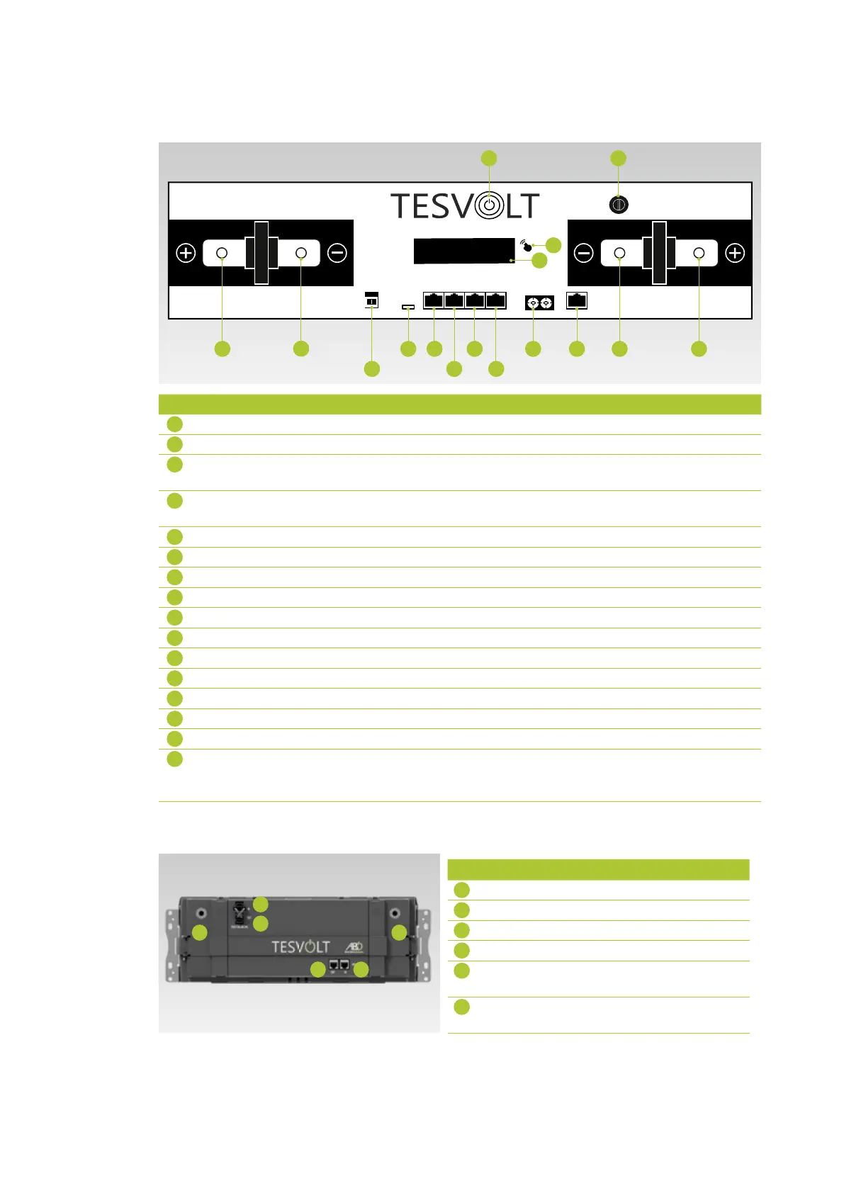
. CONNECTIONS AND STRUCTURE OF THE BATTERY MODULE
NO. DESIGNATION DESCRIPTION
17
– POLE Battery negative pole
18
+ POLE Battery positive pole
19
RACK BALANCING IN Rack balancing (input)
20
RACK BALANCING OUT Rack balancing (output)
21
BAT-COM OUT Battery module communica-
tion port (output)
22
BAT-COM IN Battery module communica-
tion port (input)
BATTERY
CHARGER
16
15
13
14
1
2
9 10 11 125 74
6 83
17
19
20
22 21
18