2.4 Conducted RF Testing
The LP-EM-CC35X1 can be used to test RF capabilities, using Radio Tool. For more information on Radio Tool
and where to download, refer to Section 2.5.1.
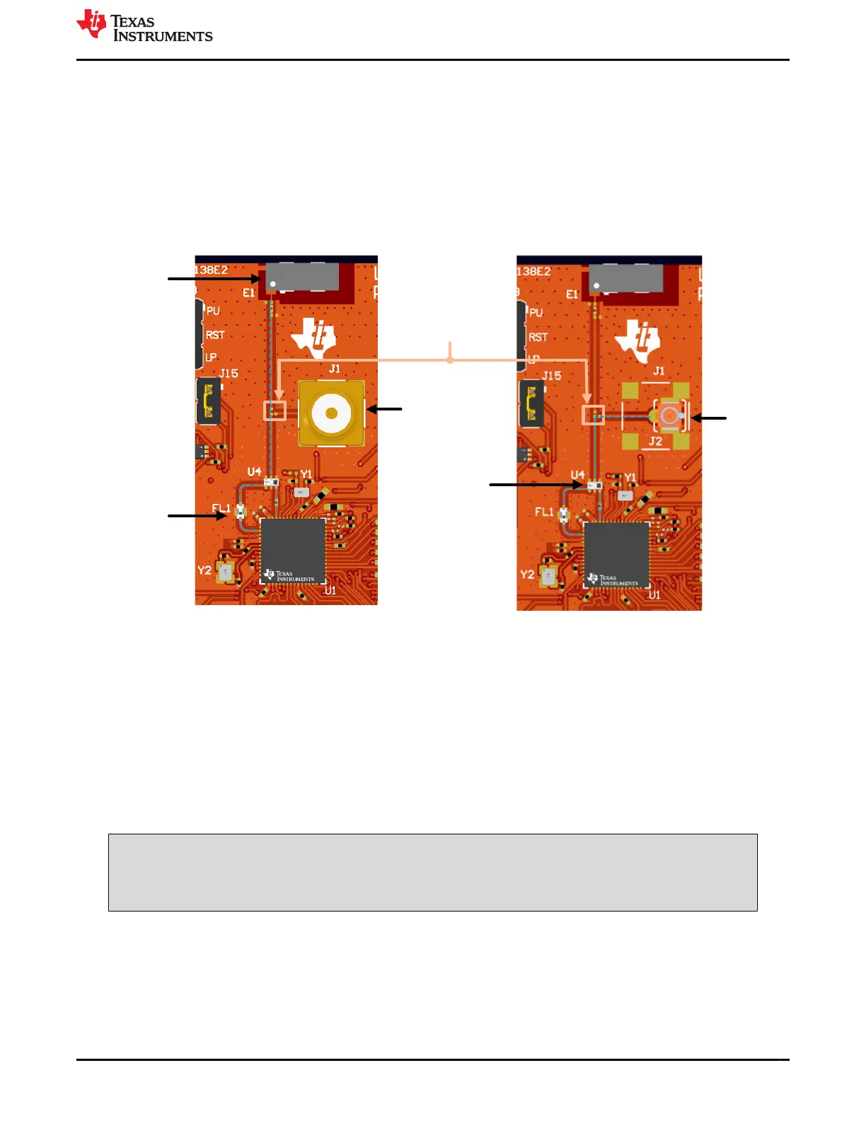
As seen in Figure 2-26, the LP-EM-CC35X1 has an on-board SMA connector and component antenna. The
SMA connector (J1) provides a way for testing conducted RF measurements. Alternately, a track pad for a U.FL
connector (J2) is provided on-board to replace the SMA connector and provide a way to test in the lab using
a compatible cable (see Figure 2-26 ). A rework is needed before using the connector on J1/J2. This involves
swapping the position of the existing 3.9pF capacitor to lead the transmission line on the desired connection (see
Figure 2-26).
Chip Antenna
2.4GHz BPF
Diplexer
SMA
connector
Mounted 3.9pF
Capacitor
U.FL
connector
Figure 2-26. RF path on LP-EM-CC35X1
2.5 Evaluation Setup
The CC35xxE Launchpad is designed to work primarily with the LP-XDS110, which provides SWD and UART
interface to external PC. The SWD interface is used for flashing the compiled image to the CC35xxE and basic
debugging, while the UART is used for serial terminal access.
The LP-XDS110 or LP-XDS110ET can easily integrate with the LP-EM-CC35X1 by connecting the 20-pin
LP-XDS110 connector (J7) to the corresponding connector on the LP-XDS110 (see Figure 2-27). Make sure that
the jumper on the LP-XDS110 (labeled TGT VDD) is in the EXT. configuration, as shown in Figure 2-27. This
verifies that the target voltage for the JTAG signals are sourced from the LP-EM-CC35X1 (which is controlled by
VIO1) instead of the default LP-XDS110 target voltage (3.3V).
WARNING
To verify proper functioning of the board, the LP-XDS110 and USB-C power cable from the LP-EM-
CC35X1 must be connected to the same computer. Do not connect the USB-C cable to a wall outlet
or different computer.
To properly interface UART signals for serial terminal interface, verify that jumpers J4 and J6 are placed in the
correct configuration. See Section 2.1.3.
For more information on the 20-pin LP-XDS110 connector and the available pinout, see Section 2.1.1.
www.ti.com Hardware
SWRU629 – SEPTEMBER 2024
Submit Document Feedback
CC35xxE LaunchPad™ Development Kit for SimpleLink™ Wi-Fi 6 and
Bluetooth® Low Energy Wireless MCU
21
Copyright © 2024 Texas Instruments Incorporated