Schematic and Bill of Materials
www.ti.com
6
SLOU410B–September 2015–Revised April 2020
Submit Documentation Feedback
Copyright © 2015–2020, Texas Instruments Incorporated
DRV425 Evaluation Module
5 Schematic and Bill of Materials
The following pages contain the DRV425EVM Bill of materials, top level silkscreen and circuit schematic
diagrams.
Table 3. Bill of Materials
DESIGNATORS DESCRIPTION MANUFACTURER MFG. PART NUMBER
C1, C2
CAP, CERM, 1 µF, 25 V, +/- 10%, X7R,
0603
Kemet C0603C105K3RACTU
J1 Header, 100mil, 4x1, Gold, R/A, TH Samtec TSW-104-08-G-S-RA
R1 RES, 100, 1%, 0.125 W, 0805 Vishay-Dale CRCW0805100RFKEA
R2, R9 RES, 10 k, 5%, 0.063 W, 0402 Vishay-Dale CRCW040210K0JNED
R3, R5, R7 RES, 0, 5%, 0.05 W, 0201 Panasonic ERJ-1GE0R00C
U1 Fluxgate Magnetic Field Sensor Texas Instruments DRV425RTJR
R4, R6, R8 Not Installed Panasonic ERJ-1GE0R00C
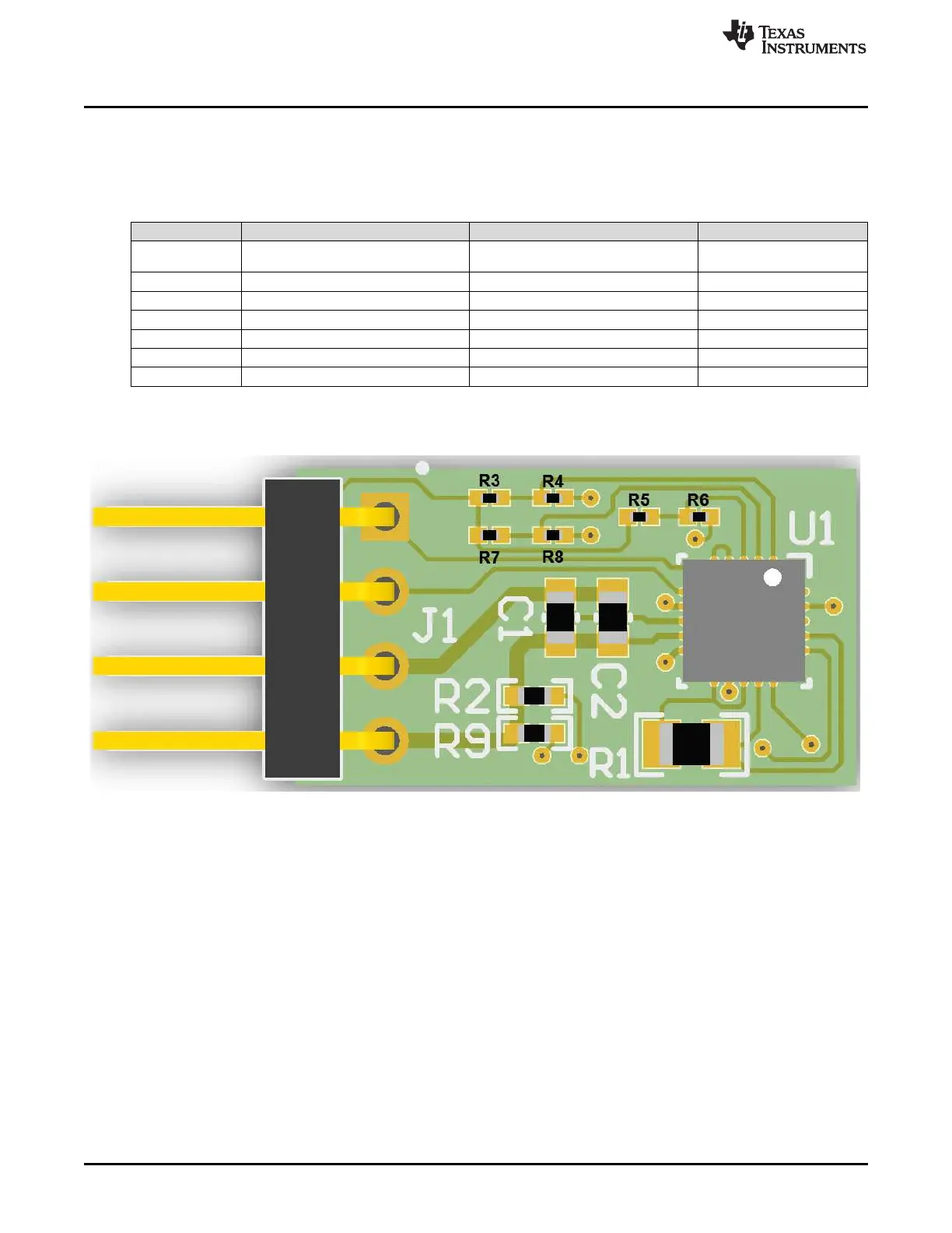
Figure 5 provides detail of the top-side layout for the DRV425EVM. Please note that resistors R3 through
R8 do not have any physical silkscreen on the printed circuit board, they are highlights below for clarity.
Figure 5. DRV425EVM Top Side Layout