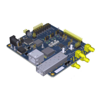
The DP83869 Evaluation Module (EVM) is a comprehensive platform designed to facilitate the evaluation and configuration of the DP83869, a low-power, fully-featured Physical Layer (PHY) transceiver. This device integrates PMD sublayers to support a wide range of Ethernet protocols, including 10BASE-T, 100BASE-TX, and 1000BASE-T for copper connections, as well as 100BASE-FX and 1000BASE-X for fiber optic connections. The EVM is optimized to demonstrate the robust EMI, EMC, and ESD performance of the DP83869, exceeding 8-kV IEC 61000-4-2 (direct contact) for ESD protection.
Function Description:
The DP83869EVM serves as a versatile tool for product and software developers to evaluate the DP83869 PHY. It supports multiple operating modes, including:
- Media Support: Seamless operation with both copper and fiber media.
- Media Conversion: Capability to convert between copper and fiber connections.
- Bridge Conversion: Supports bridging between RGMII to SGMII and SGMII to RGMII interfaces.
- MAC Interfaces: Provides both RGMII and SGMII MAC interfaces for connection to a MAC layer.
- Ethernet Protocols: Full support for 1000Base-X, 100Base-T, 100Base-TX, and 10Base-Te.
- USB-2-MDIO Support: Features an onboard MSP430 microcontroller for easy register access via USB-2-MDIO, simplifying configuration and monitoring.
- Power Supply Options: Offers onboard LDOs and external power supply options for flexible power management.
- Status LEDs: Integrated LEDs provide visual feedback for Link, Activity, and Power status.
- Hardware Configuration: Utilizes bootstraps for hardware configuration, allowing users to set various operating parameters.
The EVM is designed to demonstrate all features of the DP83869, including its ability to interface with the MAC layer in both RGMII and SGMII modes. The integrated Termination Impedance on RGMII helps reduce the system Bill of Materials (BOM).
Important Technical Specifications:
The DP83869 PHY supports a range of functional modes and configurations, which are primarily set via strap options and a 4-pin DIP switch.
- PHY Address Straps: Configurable via RX_D0 and RX_D1 pins, allowing for 4-level strap settings (Mode 0 to Mode 3) with different resistor PU/PD values (Open, 10 kΩ, 5.76 kΩ, 2.49 kΩ).
- Functional Mode Straps (OPMODE_0, OPMODE_1, OPMODE_2): These straps, controlled by JTAG_TDO/GPIO_1, RX_D3, and RX_D2 pins, define the primary operating mode of the PHY. Examples include:
- RGMII to Copper (1000Base-T/100Base-TX/10Base-Te)
- RGMII to 1000Base-X
- RGMII to 100Base-FX
- RGMII-SGMII Bridge Mode
- 1000Base-T to 1000Base-X
- 100Base-T to 100Base-FX
- SGMII to Copper (1000Base-T/100Base-TX/10Base-Te)
- JTAG for boundary scan
- Copper Ethernet Straps (ANEG_DIS, ANEGSEL_0, ANEGSEL_1, MIRROR_EN): These straps, controlled by LED_0, LED_1, LED_2, and RX_CTRL pins, configure auto-negotiation, forced speed/duplex, and MDI/MDI-X modes for copper connections.
- 1000Base-X Straps (ANEG_DIS, ANEGSEL_0): Configured via LED_0 and LED_1 pins, these straps enable or force fiber auto-negotiation and signal detect options.
- 100Base-FX Straps (ANEGSEL_0): Configured via LED_1, these straps manage signal detect options for 100Base-FX.
- Bridge Mode Straps (MIRROR_EN): Configured via RX_CTRL, these straps determine whether the EVM operates as RGMII to SGMII or SGMII to RGMII bridge.
- 100 M Media Converter Straps (ANEGSEL_0, ANEGSEL_1, MIRROR_EN, LINK_LOSS): Configured via LED_1, LED_2, RX_CTRL, and RX_CLK, these straps manage auto-negotiation, mirror functions, and link loss pass-through for 100 M media conversion.
- 1000 M Media Converter Straps (ANEG_DIS, ANEGSEL_0, ANEGSEL_1): Configured via LED_0, LED_1, and LED_2, these straps control fiber auto-negotiation and copper auto-negotiation for 1000 M media conversion.
- Clock Output: The EVM provides a 50-Ω Coax cable with an SMB connector for accessing the clock output from the PHY.
- Clock Input: The EVM is configured for a default crystal input clock operation (25-MHz crystal). It also supports external clock input from a 25-MHz CMOS oscillator or an external clock from the SMB connector, provided via a 50-Ω Coax cable.
- SGMII/Fiber Interface: SGMII pins from the DUT are multipurpose, functioning as SGMII and Fiber IO pins. By default, the EVM is configured for Fiber operation. Fiber Transceiver is not part of the EVM package.
- RGMII Interface: RGMII signals are routed to standard 2.54-mm header connectors on J14. RGMII can be used in both Copper mode and Fiber mode.
- 4-Pin DIP Switch (S1): This switch allows selection of various test modes and feature displays. Some modes can be controlled via the USB-2-MDIO GUI. The switch settings determine LED outputs (D14, D15, D16) and USB2MDIO functionality. Modes include Normal Operation, Droop Test, Clock Frequency/Master Jitter Test, Slave Jitter Test, Distortion Test, Force 100Mbps, Force 10Mbps, Reverse Loopback, XMII Loopback, and Enable BIST. Mode 15 allows continuous reading of registers from a loaded list via a serial port terminal.
Usage Features:
- Power Supply: The EVM can be powered via a J25 barrel jack connector, power-supply turrets, or a USB connection. Jumpers (J22, J34) configure the power source.
- External Voltage Rails: Jumpers (J29, J23, J21, J35, J36, J27, J33) allow selection between onboard LDOs or external power supplies for specific voltage rails (e.g., MCU_VCC, FX3V3, VDDA2P5, VDDA1P0, VDDIO, AUX_IOVDD).
- Software Utility: The onboard MSP430 is pre-programmed for use. Users need to install MSP430 drivers and the USB2MDIO software utility on a Windows PC (7 or above) to access registers.
- Register Access: The USB2MDIO software provides an interface for accessing and configuring PHY registers. For continuous register reading (Mode 15), a serial port terminal (e.g., PuTTY) can be used.
- Configuration Flexibility: The combination of strap jumpers and the 4-pin DIP switch provides extensive configuration options for different operating scenarios and testing requirements.
- Test Modes: Dedicated DIP switch modes enable various tests such as droop, clock frequency/jitter, distortion, loopbacks (reverse and XMII), and Built-In Self-Test (BIST).
Maintenance Features:
- Documentation: The user's guide provides detailed instructions on how to properly operate and configure the DP83869EVM. Associated support documents include schematic files, Bill of Materials, and best layout practices.
- Software Updates: Users are directed to the TI website for the latest MSP430 drivers, ensuring compatibility and access to the most recent features and bug fixes.
- ESD Precautions: The EVM is ESD sensitive, and users are advised to observe ESD precautions and store the evaluation kit in a protective ESD bag to prevent degradation or failure.
- Cleanliness: Assemblies must be clean and free from flux and contaminants, adhering to workmanship standards IPC-A-610 Class 2.
- Regulatory Compliance: The manual includes regulatory notices for the United States (FCC) and Canada (Industry Canada), outlining requirements for evaluation modules and radio transmitters. It also provides specific notices for EVMs delivered in Japan and for Power Line Communication, along with European Union directives for Electromagnetic Compatibility.
- Safety Warnings: The manual emphasizes that EVMs are intended for technically qualified professionals and warns against exceeding specified performance ratings, which could lead to personal injury, property damage, or unintended operation. Users are responsible for safe handling, proper isolation, and compliance with all applicable laws and regulations.