4.2 SGMII/Fiber Interface
SGMII Pins from the DUT are multipurpose pins functioning as SGMII and Fiber IO pins. By default, the EVM is
configured for Fiber operation.
Note
Fiber Transceiver is not a part of the EVM package. SFP cage and SFP connector need to be
mounted.
For routing signals to Fiber Transceiver, populate R31, R38, R45, and R47. Remove C12, C14, C15, and C17.
For routing signals to SGMII SMAs, populate C12, C14, C15, and C17. Remove R31, R38, R45, and R47.
4.3 RGMII
RGMII signals are routed to standard 2.54-mm header connectors on J14. RGMII can be used both in Copper
mode and Fiber mode.
4.4 Clock Output
The EVM has a SMB connector to output clock from the PHY. A 50-Ω Coax cable with a SMB connector needs
to be used for accessing the clock output.
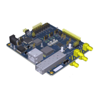
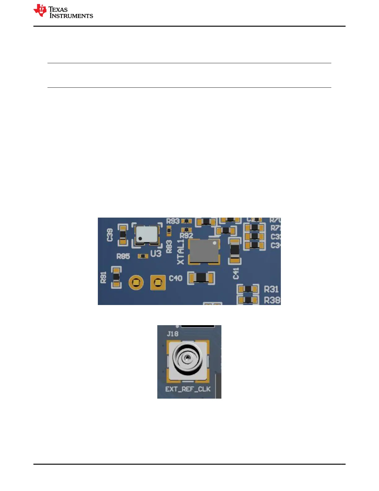
4.5 Clock Input
The EVM is configured for default crystal input clock operation. The EVM supports the option to provide clock
from 25-MHz crystal, 25-MHz CMOS oscillator, and the External clock from the SMB connector. A 50-Ω Coax
cable with a SMB connector needs to be used for providing clock input from external sources.
Figure 4-2. Onboard Clock
Figure 4-3. External Clock Input
www.ti.com Configuration Options
SNLU237A – SEPTEMBER 2018 – REVISED JANUARY 2024
Submit Document Feedback
DP83869 Evaluation Module 13
Copyright © 2024 Texas Instruments Incorporated