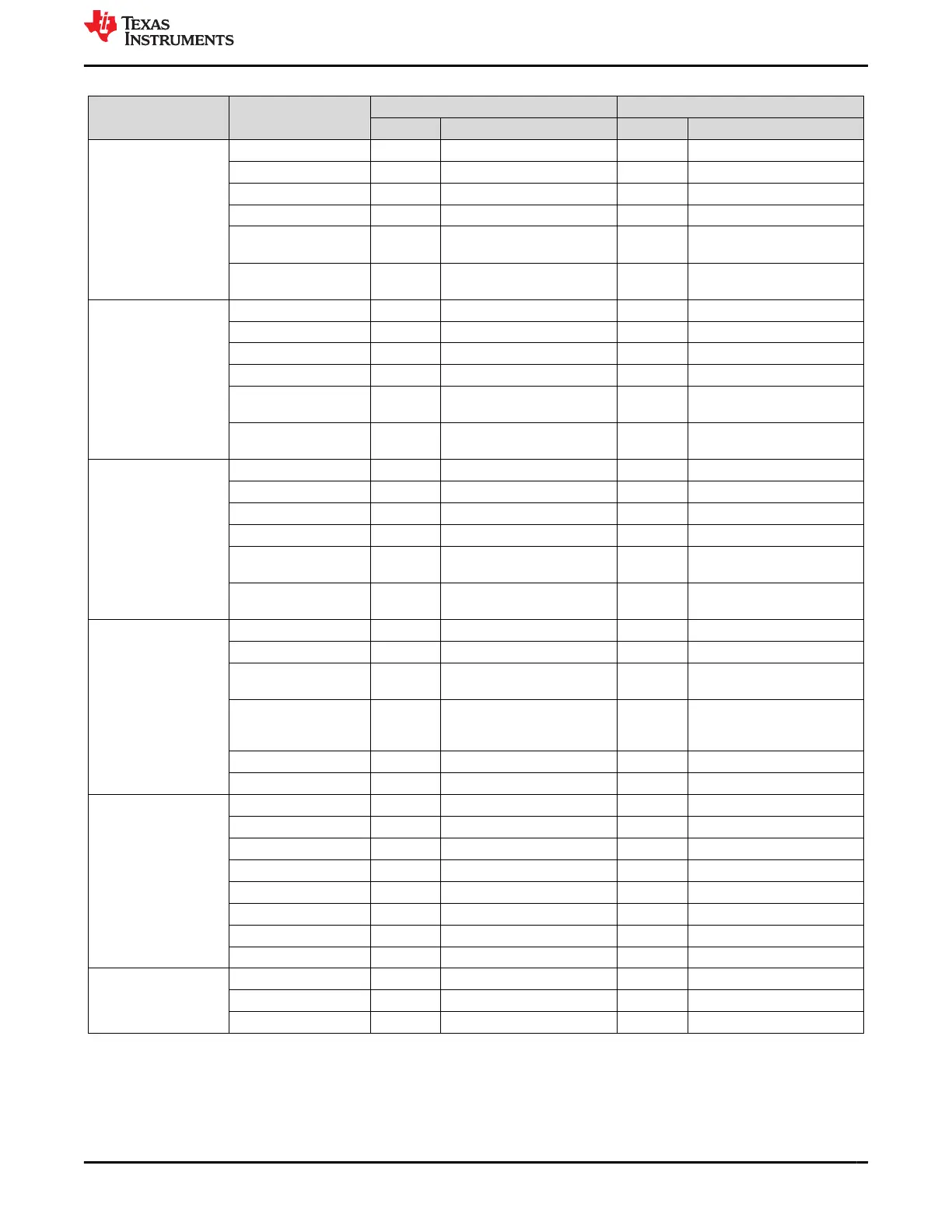
Table 5-6. GPIO NVM Settings (continued)
Register Name Field Name
TPS65941213-Q1 TPS65941111-Q1
Value Description Value Description
GPIO9_CONF GPIO9_OD 0x0 Push-pull output 0x0 Push-pull output
GPIO9_DIR 0x1 Output 0x1 Output
GPIO9_SEL 0x0 GPIO9 0x0 GPIO9
GPIO9_PU_SEL 0x0 Pull-down resistor selected 0x0 Pull-down resistor selected
GPIO9_PU_PD_EN 0x0 Disabled; Pull-up/pull-down
resistor.
0x0 Disabled; Pull-up/pull-down
resistor.
GPIO9_DEGLITCH_EN 0x0 No deglitch, only
synchronization.
0x0 No deglitch, only
synchronization.
GPIO10_CONF GPIO10_OD 0x0 Push-pull output 0x0 Push-pull output
GPIO10_DIR 0x0 Input 0x0 Input
GPIO10_SEL 0x6 WKUP1 0x7 WKUP2
GPIO10_PU_SEL 0x0 Pull-down resistor selected 0x0 Pull-down resistor selected
GPIO10_PU_PD_EN 0x1 Enabled; Pull-up/pull-down
resistor.
0x1 Enabled; Pull-up/pull-down
resistor.
GPIO10_DEGLITCH_E
N
0x1 8 us deglitch time. 0x1 8 us deglitch time.
GPIO11_CONF GPIO11_OD 0x1 Open-drain output 0x0 Push-pull output
GPIO11_DIR 0x1 Output 0x1 Output
GPIO11_SEL 0x2 NRSTOUT_SOC 0x0 GPIO11
GPIO11_PU_SEL 0x0 Pull-down resistor selected 0x0 Pull-down resistor selected
GPIO11_PU_PD_EN 0x0 Disabled; Pull-up/pull-down
resistor.
0x0 Disabled; Pull-up/pull-down
resistor.
GPIO11_DEGLITCH_E
N
0x0 No deglitch, only
synchronization.
0x0 No deglitch, only
synchronization.
NPWRON_CONF NPWRON_SEL 0x0 ENABLE 0x0 ENABLE
ENABLE_PU_SEL 0x0 Pull-down resistor selected 0x0 Pull-down resistor selected
ENABLE_PU_PD_EN 0x1 Enabled; Pull-up/pull-down
resistor.
0x1 Enabled; Pull-up/pull-down
resistor.
ENABLE_DEGLITCH_E
N
0x1 8 us deglitch time when
ENABLE, 50 ms deglitch time
when NPWRON.
0x1 8 us deglitch time when
ENABLE, 50 ms deglitch time
when NPWRON.
ENABLE_POL 0x0 Active high 0x0 Active high
NRSTOUT_OD 0x1 Open-drain output 0x1 Open-drain output
GPIO_OUT_1 GPIO1_OUT 0x0 Low 0x0 Low
GPIO2_OUT 0x0 Low 0x0 Low
GPIO3_OUT 0x0 Low 0x0 Low
GPIO4_OUT 0x0 Low 0x0 Low
GPIO5_OUT 0x0 Low 0x0 Low
GPIO6_OUT 0x0 Low 0x0 Low
GPIO7_OUT 0x0 Low 0x0 Low
GPIO8_OUT 0x0 Low 0x0 Low
GPIO_OUT_2 GPIO9_OUT 0x0 Low 0x0 Low
GPIO10_OUT 0x0 Low 0x0 Low
GPIO11_OUT 0x0 Low 0x0 Low
5.7 Finite State Machine (FSM) Settings
These settings describe how the PMIC output rails are assigned to various system-level states. Also, the default
trigger for each system-level state is described. All these settings can be changed though I
2
C after startup.
www.ti.com Static NVM Settings
SLVUC99 – JANUARY 2022
Submit Document Feedback
Optimized Dual TPS6594-Q1 PMIC User Guide for Jacinto
™
7 DRA829 or
TDA4VM Automotive PDN-0C
23
Copyright © 2022 Texas Instruments Incorporated
 Loading...


