5.4 LDO Settings
These settings detail the voltages, configurations, and monitoring of the LDO rails stored in the NVM. All these
settings can be changed though I
2
C after startup. Some settings, typically the enable bits, are also changed by
the PFSM, as described in Section 6.3.
After the Section 6.3.8 sequence has completed, the LDOx_EN and LDOx_VMON_EN bits are set and the
LDOx_RV_SEL bit is cleared for all LDOs. The other bits will remain unchanged, but are still accessible via I
2
C.
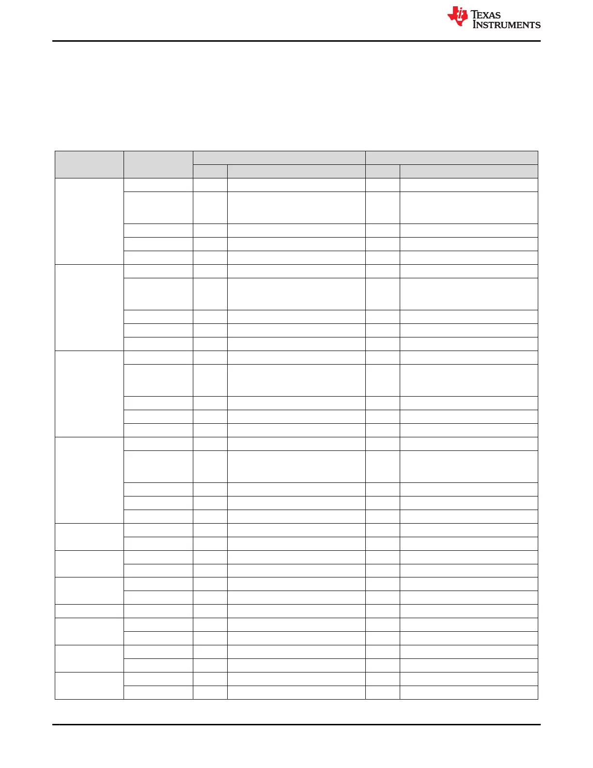
Table 5-4. LDO NVM Settings
Register Name Field Name
TPS65941213-Q1 TPS65941111-Q1
Value Description Value Description
LDO1_CTRL LDO1_EN 0x0 Disabled; LDO1 regulator. 0x0 Disabled; LDO1 regulator.
LDO1_SLOW_RA
MP
0x0 25mV/us max ramp up slew rate for
LDO output from 0.3V to 90% of
LDOn_VSET
0x0 25mV/us max ramp up slew rate for
LDO output from 0.3V to 90% of
LDOn_VSET
LDO1_PLDN 0x1 125 Ohm 0x1 125 Ohm
LDO1_VMON_EN 0x0 Disable OV and UV comparators. 0x0 Disable OV and UV comparators.
LDO1_RV_SEL 0x1 Enabled 0x1 Enabled
LDO2_CTRL LDO2_EN 0x0 Disabled; LDO2 regulator. 0x0 Disabled; LDO2 regulator.
LDO2_SLOW_RA
MP
0x0 25mV/us max ramp up slew rate for
LDO output from 0.3V to 90% of
LDOn_VSET
0x0 25mV/us max ramp up slew rate for
LDO output from 0.3V to 90% of
LDOn_VSET
LDO2_PLDN 0x1 125 Ohm 0x1 125 Ohm
LDO2_VMON_EN 0x0 Disabled; OV and UV comparators. 0x0 Disabled; OV and UV comparators.
LDO2_RV_SEL 0x1 Enabled 0x1 Enabled
LDO3_CTRL LDO3_EN 0x0 Disabled; LDO3 regulator. 0x0 Disabled; LDO3 regulator.
LDO3_SLOW_RA
MP
0x0 25mV/us max ramp up slew rate for
LDO output from 0.3V to 90% of
LDOn_VSET
0x0 25mV/us max ramp up slew rate for
LDO output from 0.3V to 90% of
LDOn_VSET
LDO3_PLDN 0x1 125 Ohm 0x1 125 Ohm
LDO3_VMON_EN 0x0 Disabled; OV and UV comparators. 0x0 Disabled; OV and UV comparators.
LDO3_RV_SEL 0x1 Enabled 0x1 Enabled
LDO4_CTRL LDO4_EN 0x0 Disabled; LDO4 regulator. 0x0 Disabled; LDO4 regulator.
LDO4_SLOW_RA
MP
0x0 25mV/us max ramp up slew rate for
LDO output from 0.3V to 90% of
LDOn_VSET
0x0 25mV/us max ramp up slew rate for
LDO output from 0.3V to 90% of
LDOn_VSET
LDO4_PLDN 0x1 125 Ohm 0x1 125 Ohm
LDO4_VMON_EN 0x0 Disabled; OV and UV comparators. 0x0 Disabled; OV and UV comparators.
LDO4_RV_SEL 0x1 Enabled 0x1 Enabled
LDO1_VOUT LDO1_VSET 0x1c 1.80 V 0x3a 3.30 V
LDO1_BYPASS 0x0 Linear regulator mode. 0x1 Bypass mode.
LDO2_VOUT LDO2_VSET 0x1c 1.80 V 0x3a 3.30 V
LDO2_BYPASS 0x0 Linear regulator mode. 0x1 Bypass mode.
LDO3_VOUT LDO3_VSET 0x8 0.80 V 0x1c 1.80 V
LDO3_BYPASS 0x0 Linear regulator mode. 0x0 Linear regulator mode.
LDO4_VOUT LDO4_VSET 0x38 1.800 V 0x38 1.800 V
LDO1_PG_WIND
OW
LDO1_OV_THR 0x3 +5% / +50 mV 0x3 +5% / +50 mV
LDO1_UV_THR 0x3 -5% / -50 mV 0x3 -5% / -50 mV
LDO2_PG_WIND
OW
LDO2_OV_THR 0x3 +5% / +50 mV 0x3 +5% / +50 mV
LDO2_UV_THR 0x3 -5% / -50 mV 0x3 -5% / -50 mV
LDO3_PG_WIND
OW
LDO3_OV_THR 0x3 +5% / +50 mV 0x3 +5% / +50 mV
LDO3_UV_THR 0x3 -5% / -50 mV 0x3 -5% / -50 mV
Static NVM Settings www.ti.com
20 Optimized Dual TPS6594-Q1 PMIC User Guide for Jacinto
™
7 DRA829 or
TDA4VM Automotive PDN-0C
SLVUC99 – JANUARY 2022
Submit Document Feedback
Copyright © 2022 Texas Instruments Incorporated
 Loading...


