www.ti.com
Hardware
13
SLAU772A–June 2018–Revised March 2020
Submit Documentation Feedback
Copyright © 2018–2020, Texas Instruments Incorporated
MSP430G2553 LaunchPad™ Development Kit (MSP
‑
EXP430G2ET)
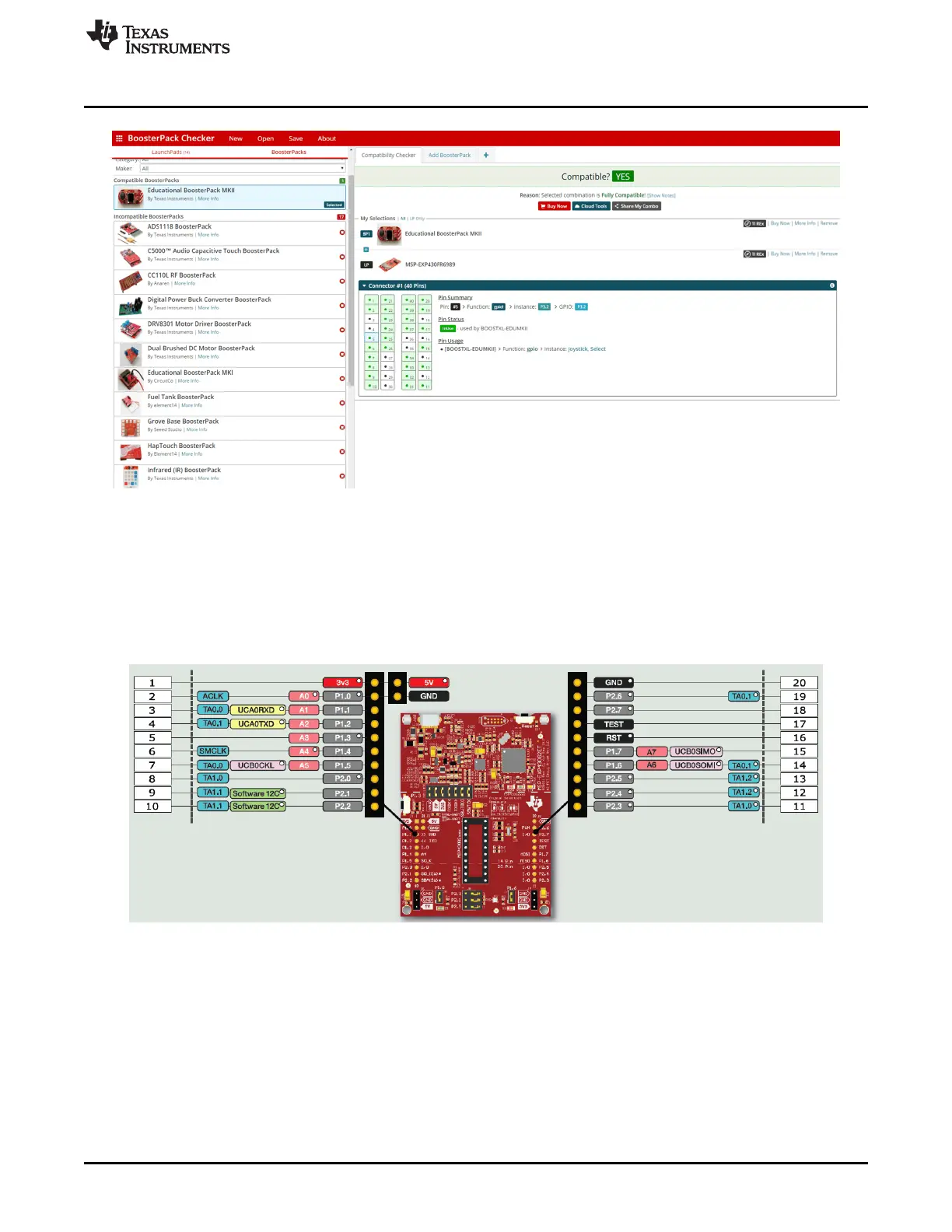
Figure 9. BoosterPack Checker Tool
Figure 10 shows the 20-pin pinout of the connector from the LaunchPad development kit to a BoosterPack
plug-in module.
Software configuration of the pin functions plays a role in compatibility. The LaunchPad development kit
side of the dashed line shows only the applicable function for conforming to the standard. However, each
pin has other functionality that can be configured by the software. See the MSP430G2553 data sheet for
more details on individual pin functions.
Figure 10. Pinout of Connector From LaunchPad Development Kit to BoosterPack Plug-in Module
2.8 20-Pin DIP Socket
The MSP-EXP430G2ET comes with the MSP430G2553 MCU plugged into the DIP target socket.
However, both PDIP14 and PDIP20 packages of the MSP430G2xx entry-level MCUs and the
MSP430F20xx MCUs can be inserted into the DIP socket aligned to pin 1 (see Figure 11). For a complete
list of supported MCUs, see Section 2.9.

 Loading...


