Hardware
www.ti.com
8
SLAU772A–June 2018–Revised March 2020
Submit Documentation Feedback
Copyright © 2018–2020, Texas Instruments Incorporated
MSP430G2553 LaunchPad™ Development Kit (MSP
‑
EXP430G2ET)
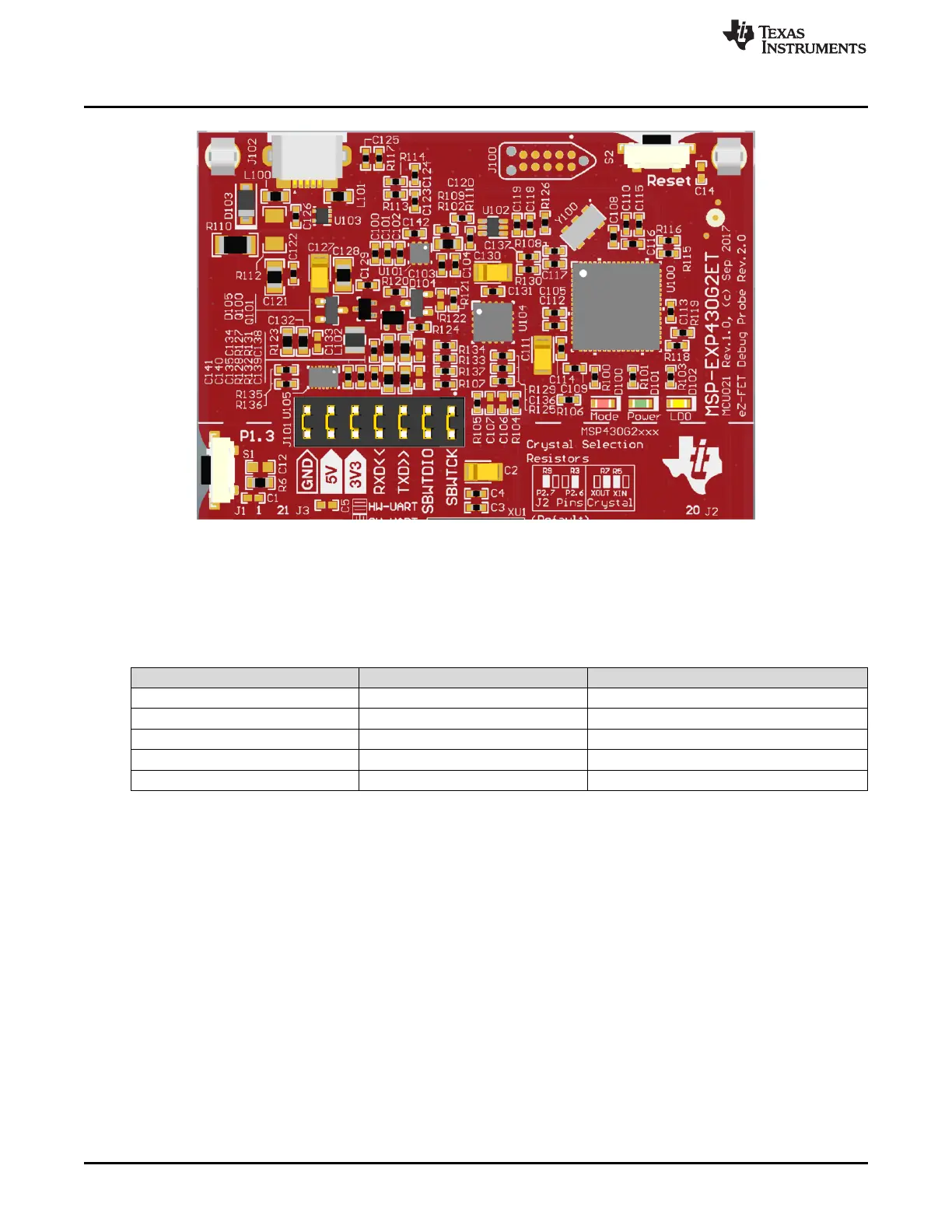
Figure 5. eZ-FET Debug Probe
The MSP-EXP430G2ET LaunchPad development kit features EnergyTrace technology but does not have
support for EnergyTrace++ technology (see Table 1). The EnergyTrace technology functionality varies
across the MSP430 portfolio.
Table 1. EnergyTrace Technology
Features EnergyTrace Technology EnergyTrace++ Technology
Current monitoring ✓ ✓
CPU state ✓
Peripheral and system states ✓
Devices supported All MSP430 MCUs MSP430FR59xx and MSP430FR69xx MCUs
Development tool required MSP-FET or eZ-FET MSP-FET or eZ-FET
The dotted line through J101 shown in Figure 5 divides the eZ-FET debug probe from the target area. The
signals that cross this line can be disconnected by jumpers on J101, the isolation jumper block. For details
on the isolation jumper block, see Section 2.2.3.
The eZ-FET also provides a backchannel UART-over-USB connection with the host, which can be very
useful during debugging and for easy communication with a PC. For details on the backchannel
connection, see Section 2.2.4.
For more information about the eZ-FET hardware, see the schematics in Section 6 and the Hardware
Design Files. For more information about the software and the debugger, see the eZ-FET wiki.
2.2.3 Debug Probe Connection: Isolation Jumper Block
The isolation jumper block at jumper J101 allows the user to connect or disconnect signals that cross from
the eZ-FET domain into the MSP430G2553 target domain. This includes eZ-FET Spy-Bi-Wire signals,
application UART signals, and 3.3-V and 5-V power.
Reasons to open these connections:
• To remove any and all influence from the eZ-FET debug probe for high-accuracy target power
measurements

 Loading...


