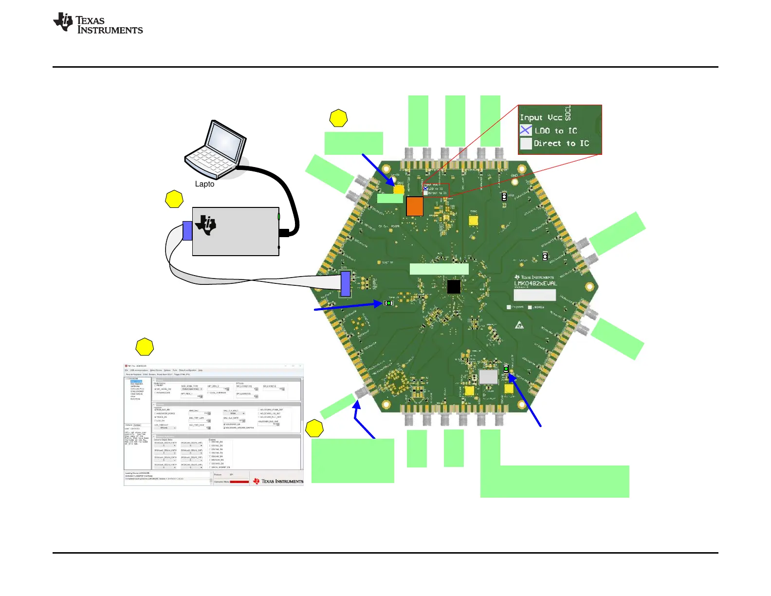
4 to 5 V
CLKin
1*
Reference clock from
signal generator or other
external source.
122.88 MHz (Default)
LMK0482x
DCLKout
2
DCLKout
2
*
SDCLKout
11
*
SDCLKout
11
DCLKout3*
DCLKout3
OSCout
OSCout*
CLKin0
CLKin0*
OSCin
OSCin*
These SMAs not used by default.
With PCB change, can be used for reference
input for single PLL mode.
SDCLKout1*
SDCLKout1
DCLKout0*
DCLKout0
DCLKout
10
*
DCLKout
10
Default is
LDO to IC
PLL1 Digital Lock Detect LED
PLL2 Digital
Lock Detect LED
2
Reference
VCC
GND
VCC
1
Power
Laptop or PC
3
USB cable
USB2ANY
USB2ANY
Texas Instruments
HPA665
Å BSL
Button
5
Program with TICS Pro
%HVXUHWRSUHVV³&WUO+/´RU
USB communications Æ Write All Registers
10-Pin Ribbon Cable
www.ti.com
Quick Start
3
SNAU145B–MAY 2013–Revised March 2018
Submit Documentation Feedback
Copyright © 2013–2018, Texas Instruments Incorporated
LMK04826 and LMK04828 User’s Guide
2 Quick Start
Figure 1. Quick Start Diagram