Data Frame
Three control bytes (D1 to D3) determine the selected baud rate. D1 and D2 set the processor frequency
(f ≥ f
min
), D3 indirectly sets the flash timing generator frequency (f
FTGmin
≤ f
FTG
≤ f
FTGmax
). In detail:
D1: F1xx: Basic clock module control register DCOCTL (DCO.2 ... DCO.0)
F2xx: Basic clock module control register DCOCTL (DCO.2 ... DCO.0)
F4xx: FLL+ system clock control register SCFI0 (D, FN_8 ... FN_2)
D2: F1xx: basic clock module control register BCSCTL1 (XT2Off, Rsel.2 ... Rsel.0)
F2xx: basic clock module control register BCSCTL1 (XT2Off, Rsel.2 ... Rsel.0)
F4xx: FLL+ system clock control register SCFI1 (N
DCO
)
D3 0: 9600 Baud
1: 19200 Baud
2: 38400 Baud
After receiving the data frame, an acknowledge character DATA_ACK is sent back, and the BSL becomes
prepared for the selected baud rate. It is recommended for the BSL communication program to wait
approximately 10 ms between baud rate alteration and succeeding data transmission to give the BSL
clock system time for stabilization.
Note: The highest achievable baud rate depends on various system and environment
parameters like supply voltage, temperature range, and minimum/maximum processor
frequency. See the corresponding device specification/data sheet.
Note: This command is implemented on BSL versions V1.60 or higher or available in the
loadable bootstrap loader BL_150S_14x.txt.
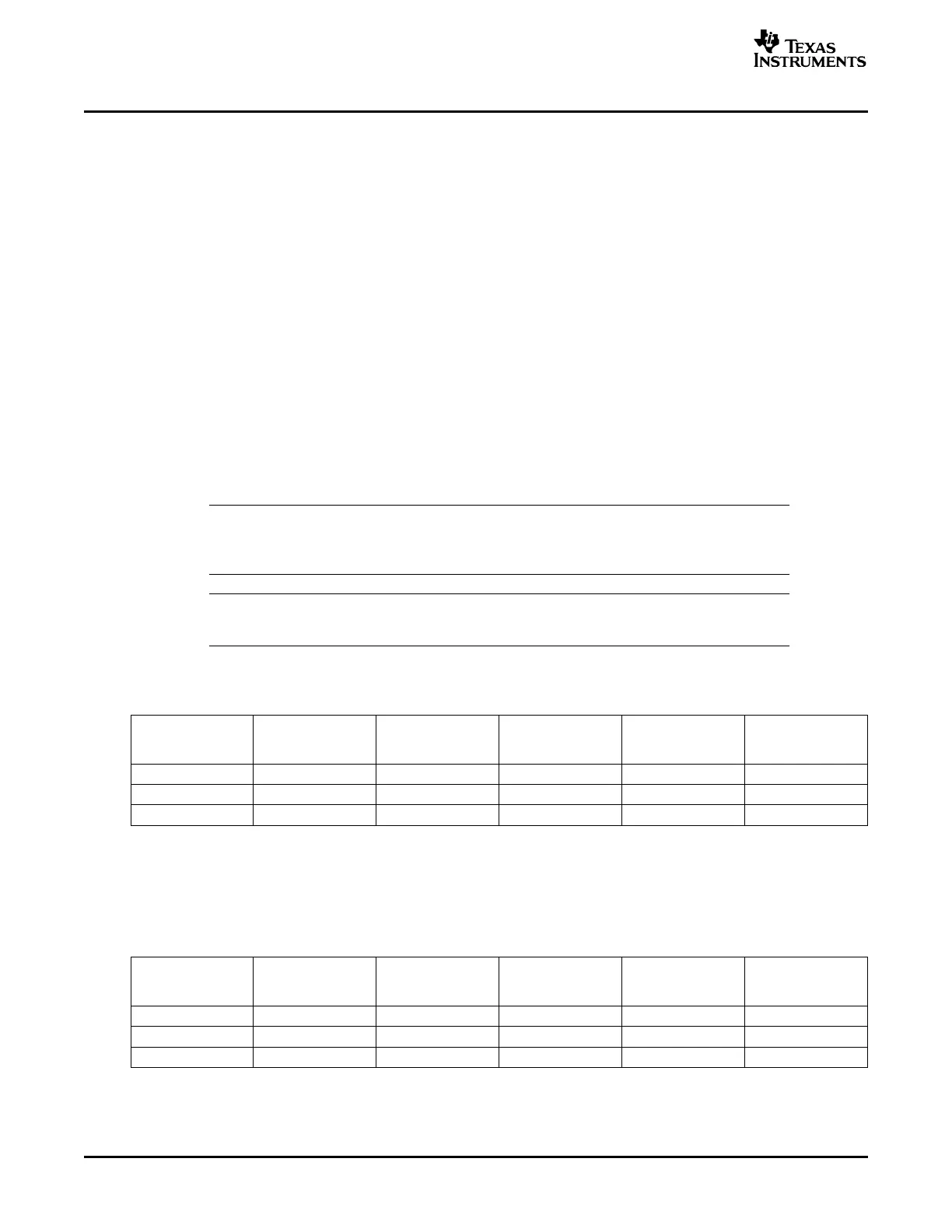
Table 2. Recommendations for MSP430F149 [F449]
(1)
(T
A
= 25 ° C, V
CC
= 3.0 V, f
max
= 6.7 MHz)
PROCESSOR PROGRAM/VERIFY
BAUD RATE D1 DCOCTL D2 BCSCTL1
FREQUENCY, f
min
D3
(3)
60 Kbytes
(Baud) [SCFI0]
(3)
[SCFI1]
(3)
(MHz)
(2)
(sec)
(4)
9600 (init) 1.05 0x80 [00] 0x85 [98] 00 [00] 78 + 3.7 [0.0]
19200 2.1 0xE0 [00] 0x86 [B0] 01 [01] 39 + 3.7 [2.4]
38400 4.2 0xE0 [00] 0x87 [C8] 02 [02] 20 + 3.7 [2.4]
(1)
Values in brackets [ ] are related to MSP430F449.
(2)
The minimum processor frequency is lower than in the standard ROM BSL (see Section 12.3 , Initialization Status).
(3)
D1 to D3 are bytes in hexadecimal notation.
(4)
Additional 3.7 [2.4] seconds result from loading, verifying, and launching the loadable BSL.
Table 3. Recommendations for MSP430F2131
(1)
(T
A
= 25 ° C, V
CC
= 3.0 V, f
max
= 6.7 MHz)
PROCESSOR PROGRAM/VERIFY
BAUD RATE D1 DCOCTL D2 BCSCTL1
FREQUENCY, f
min
D3
(3)
60 Kbytes
(Baud) [SCFI0]
(3)
[SCFI1]
(3)
(MHz)
(2)
(sec)
9600 (init) 1.05 0x80 0x85 00 78
19200 2.1 0x00 0x8B 01 39
38400 4.2 0x80 0x8C 02 20
(1)
Values in brackets [ ] are related to MSP430F449.
(2)
The minimum processor frequency is lower than in the standard ROM BSL (see Section 12.3 , Initialization Status).
(3)
D1 to D3 are bytes in hexadecimal notation.
Features of the MSP430 Bootstrap Loader10 SLAA089D – December 1999 – Revised August 2006
Submit Documentation Feedback