2.2 MSP430 Flash Devices With Dedicated JTAG Pins
RST
DTR
/NMI
( )
TEST
( )RTS
Bootstrap Loader Starts
3 UART Protocol
UART Protocol
The TEST signal is normally used simply to switch the port pins P1.7 to P1.4 between their application
function and the JTAG function. If the second rising edge at the TEST pin is applied while RST/NMI is still
low, the TEST signal is kept low internally (application mode).
The BSL will not be started (via the BSL RESET vector), if:
• There are less than two positive edges at the TEST pin while RST/NMI is low
• TEST is low when RST/NMI rises from low to high
• JTAG has control over the MSP430 resources
• Supply voltage, V
CC
, drops down and a power-on reset (POR) is executed
• RST/NMI pin is configured for NMI functionality (NMI bit is set)
Note: The minimum timing for this sequence must be within the limits specified for the
corresponding pin in the datasheet.
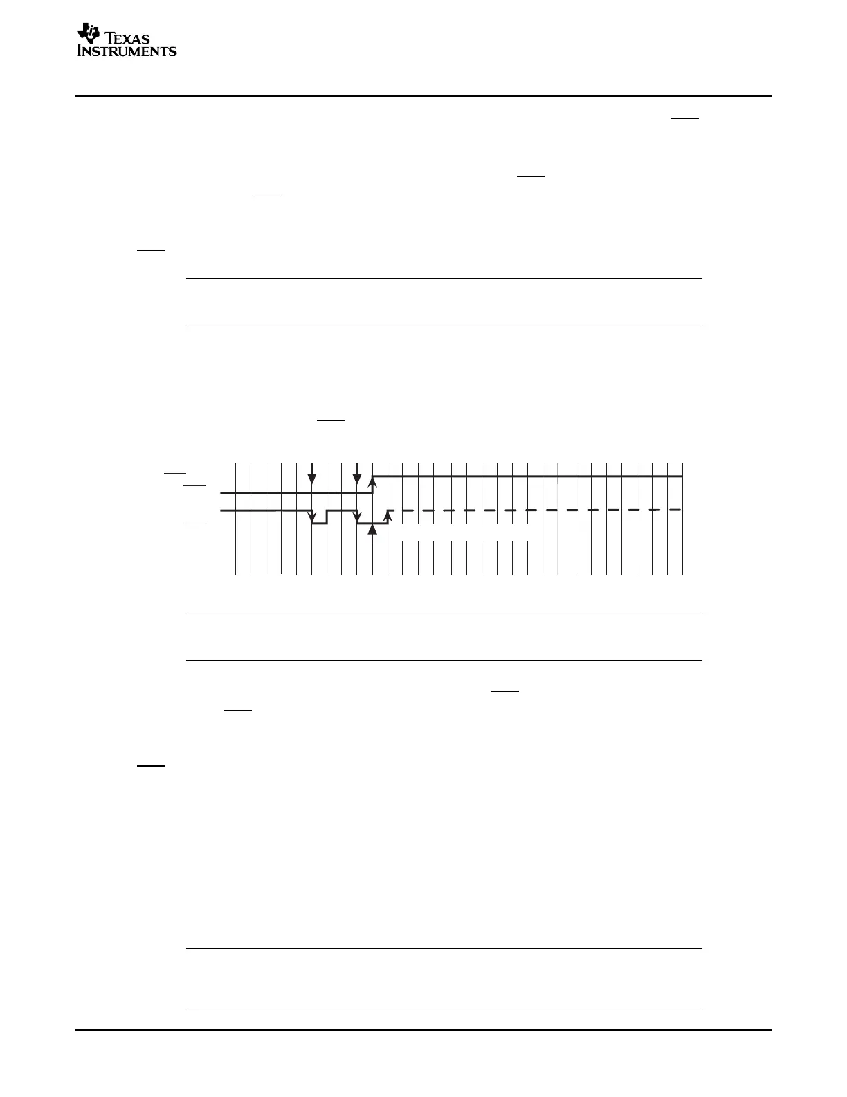
Devices with dedicated JTAG pins use the TCK pin instead of the TEST pin.
The BSL program execution starts whenever the TCK pin has received a minimum of two negative
transitions and TCK is low while RST/NMI rises from low to high (BSL entry method, see Figure 3 ). This
level/transition triggering improves BSL start-up reliability.
Figure 3. BSL Entry Sequence at Dedicated JTAG Pins
Note: The minimum timing for this sequence has to be within the limits specified for the
corresponding pin in the datasheet.
The BSL will not be started (via the BSL RESET vector), if:
• There are less than two negative edges at TCK pin while RST/NMI is low
• TCK is high if RST/NMI rises from low to high
• JTAG has control over the MSP430 resources
• Supply voltage, V
CC
, drops down, and a power-on reset (POR) is executed
• RST/NMI pin is configured for NMI functionality (NMI bit is set)
The UART protocol applied here is defined as:
• Baud rate is fixed to 9600 baud in half duplex mode (one sender at a time).
• Start bit, 8 data bits (LSB first), an even parity bit, 1 stop bit.
• Handshake is performed by an acknowledge character.
• Minimum time delay before sending new characters after characters have been received from the
MSP430 BSL: 1.2 ms
Note: Applying baud rates other than 9600 baud at initialization results in communication
problems or violates the flash memory write timing specification. The flash memory may
be extensively stressed or may react with unreliable program/erase operations.
SLAA089D – December 1999 – Revised August 2006 Features of the MSP430 Bootstrap Loader 3
Submit Documentation Feedback