1 Introduction
2 Standard RESET and BSL Entry Sequence
2.1 MSP430 20- and 28-Pin Flash Devices With Shared JTAG Pins
RST
DTR
/NMI
( )
TEST
( )RTS
User Program Starts
Bootstrap Loader Starts
RST
DTR
/NMI
( )
TEST
( )RTS
Introduction
This bootstrap loader (BSL) provides a method to program the flash memory during MSP430 project
development and updates. It can be activated by a utility that sends commands via the familiar UART
protocol. The BSL enables the user to control the activity of the MSP430 and to exchange data using a
personal computer or other device that supports a UART protocol.
To avoid accidental overwriting of the BSL code, this code is stored in a special factory-masked boot
ROM. The BSL cannot ever be erased. The BSL code is highly optimized for the BSL function and is
accessed using commands described later in this document. For security purposes and to prevent
unwanted source readout, user code protection is very important. Any BSL command that directly or
indirectly allows data reading is password protected.
To invoke the bootstrap loader, a BSL entry sequence has to be applied to dedicated pins. After that, a
synchronization character, followed by the data frame of a specific command, initiates the desired
function.
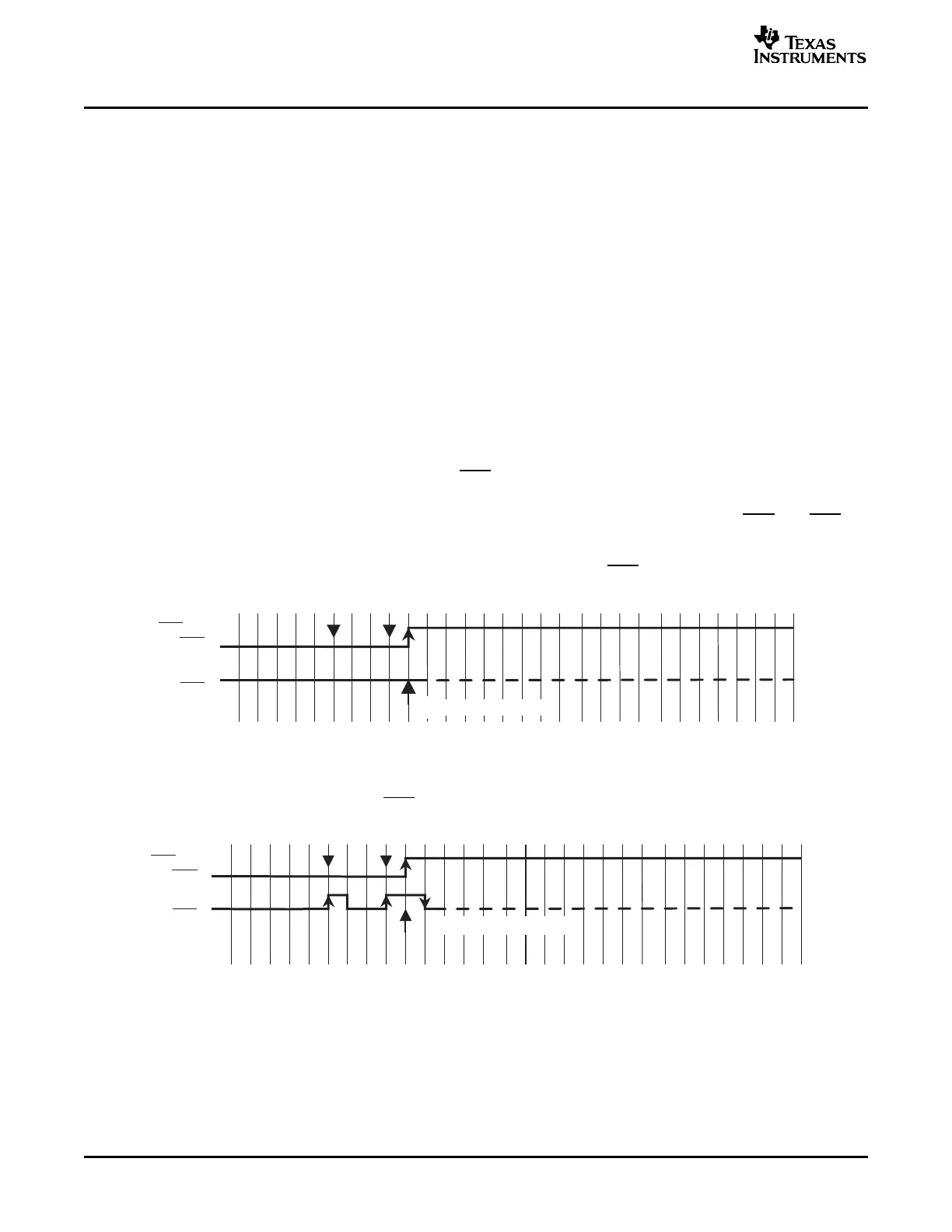
Applying an appropriate entry sequence on the RST/NMI and TEST pins forces the MSP430 to start
program execution at the BSL RESET vector instead of at the RESET vector located at address FFFEh.
If the application interfaces with a computer UART, these two pins may be driven by the DTR and RTS
signals of the serial communication port (RS232) after passing level shifters. Detailed descriptions of the
hardware and related considerations are given in a separate document (see Section 14 References). The
normal user reset vector at FFFEh is used, if TEST is kept low while RST/NMI rises from low to high
(standard method, see Figure 1 ).
Figure 1. Standard RESET Sequence
The BSL program execution starts whenever the TEST pin has received a minimum of two positive
transitions and if TEST is high while RST/NMI rises from low to high (BSL entry method, see Figure 2 ).
This level/transition triggering improves BSL startup reliability.
Figure 2. BSL Entry Sequence at Shared JTAG Pins
2 Features of the MSP430 Bootstrap Loader SLAA089D – December 1999 – Revised August 2006
Submit Documentation Feedback