Target Device
MSP432P401R
Crystal
48 MHz
Micro‐B
USB
EnergyTrace+
Current
Measure HW
LDO
5 V, 3.3 V
ESD
Protection
Power
Switch
Debug
MCU
LED
Red, Green
Power, UART, JTAG to Target
User Interface
Buttons and LEDs
40‐pin LaunchPad
standard headers
{
EnergyTrace Technology
Real-time power consumption
readings and state updates from the
MSP432P401R MCU viewable
through the EnergyTrace GUI
40-pin BoosterPack
plug-in module connector
(J1–J4)
{
Button/Switch
S2
User LEDs
LED1 and LED2
Button/Switch
S1
Fanout of Unused Pins
- Access to unused pins on the
MSP432P401R device
- Support for bread-board connection
MSP432P401R Microcontroller
MSP1
{
Jumper Isolation Block
- J101
- Power
- GND, 5V, and 3V3
- Back-channel UART to the PC
- RXD, TXD
- JTAG
- RST, TMS, TCK, TDO, TDI
XDS110 onboard debug probe
Enables debugging and programming
as well as communication to the PC.
The XDS110 can also provide power
to the target MCU.
Reset
MSP432P401R Reset
www.ti.com
Hardware
5
SLAU597E–March 2015–Revised January 2018
Submit Documentation Feedback
Copyright © 2015–2018, Texas Instruments Incorporated
MSP432P401R SimpleLink™ Microcontroller LaunchPad™ Development Kit
(MSP
‑
EXP432P401R)
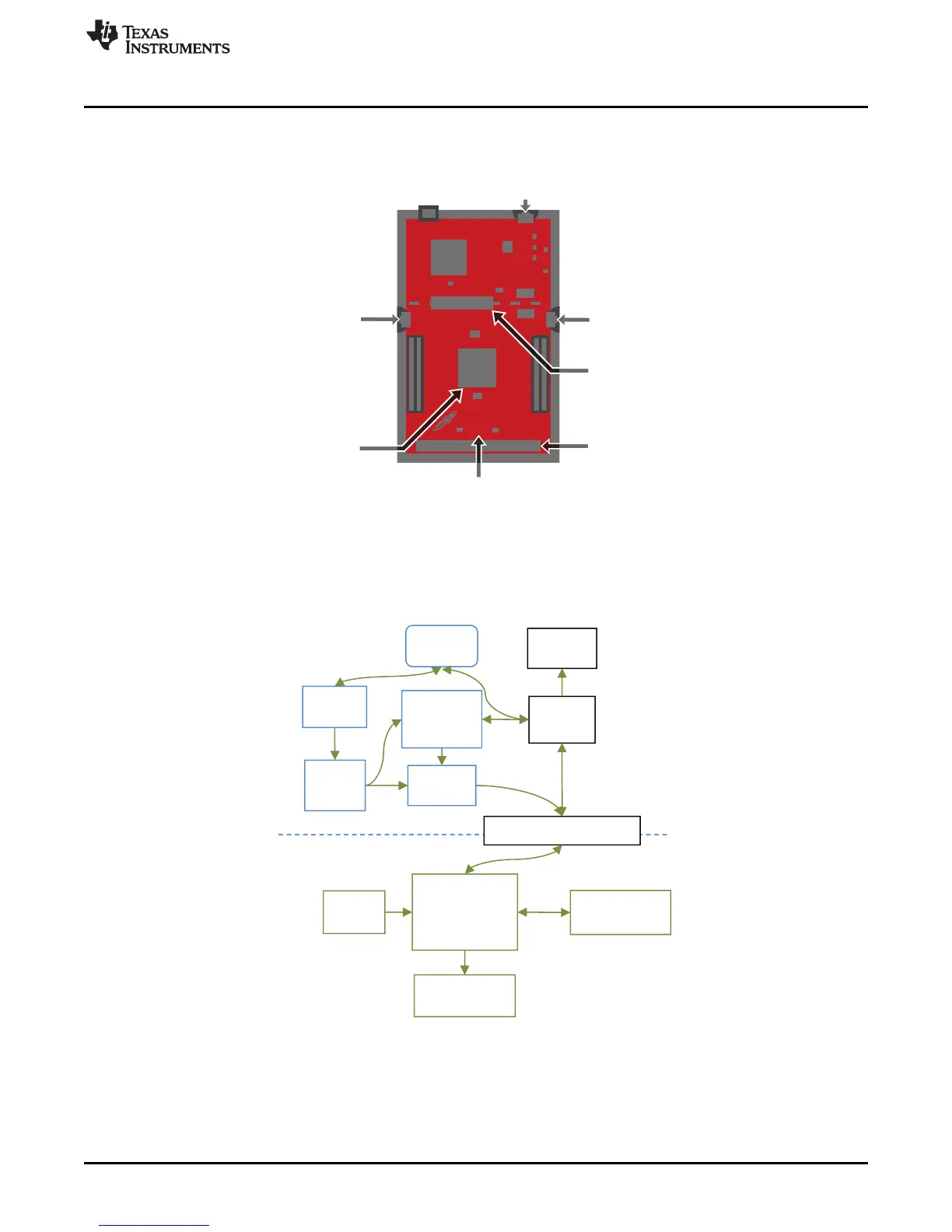
2 Hardware
Figure 2 shows an overview of the EVM hardware.
Figure 2. MSP-EXP432P401R Overview
2.1 Block Diagram
Figure 3 shows the block diagram.
Figure 3. Block Diagram

 Loading...


