www.ti.com
Hardware
7
SLAU597E–March 2015–Revised January 2018
Submit Documentation Feedback
Copyright © 2015–2018, Texas Instruments Incorporated
MSP432P401R SimpleLink™ Microcontroller LaunchPad™ Development Kit
(MSP
‑
EXP432P401R)
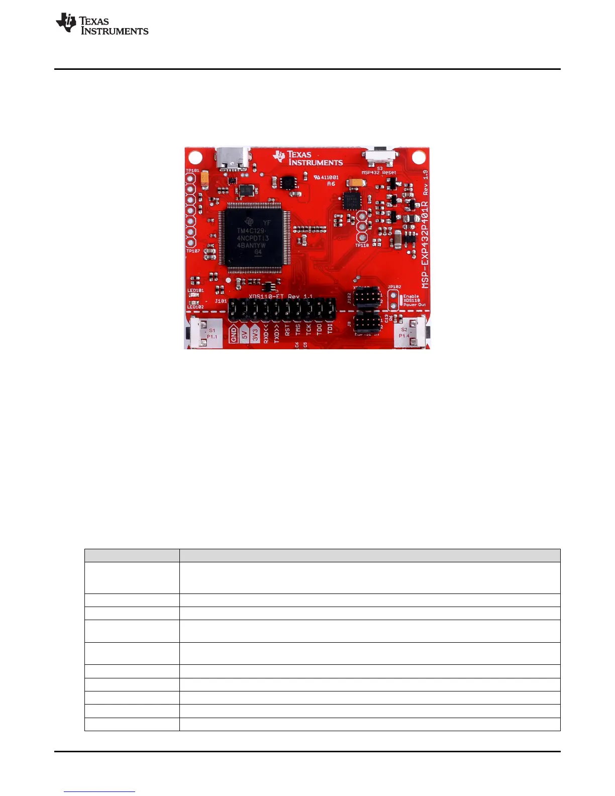
2.3 XDS110-ET Onboard Debug Probe
To keep development easy and cost effective, TI's LaunchPad development kits integrate an onboard
debug probe, which eliminates the need for expensive programmers. The MSP‑EXP432P401R has the
XDS110-ET debug probe, which is a simple low-cost debug probe that supports nearly all TI ARM device
derivatives.
Figure 5. XDS110-ET Debug Probe
The XDS110-ET hardware can be found in the schematics in Section 6 and in the MSP‑EXP432P401R
Hardware Design Files.
2.3.1 XDS110-ET Isolation Block J101
The J101 isolation block is composed of J101 jumpers shown in Table 1. The J101 isolation block allows
the user to connect or disconnect signals that cross from the XDS110-ET domain into the MSP432P401R
target domain. This crossing is shown by the silkscreen dotted line across the LaunchPad development kit
through J101. No other signals cross the domain, so the XDS110-ET can be completely decoupled from
the MSP432P401R target side. This includes XDS110-ET power and GND signals, UART, and JTAG
signals.
Table 1 lists the signals that are controlled at the isolation block.
Table 1. Isolation Block Connections
Signal Description
GND
GND power connection between XDS110 and MSP432 target GND planes. The GND jumper is
populated to connect the separate GND planes. This connection is required for proper operation with
3V3, 5V, UART, and JTAG.
5V 5-V power rail, VBUS from USB
3V3 3.3-V power rail, derived from VBUS by an LDO in the XDS110-ET domain
RXD <<
Backchannel UART: The target MCU receives data through this signal. The arrows indicate the direction
of the signal.
TXD >>
Backchannel UART: The target MCU sends data through this signal. The arrows indicate the direction of
the signal.
RST MCU RST signal (active low)
TCK_SWCLK Serial wire clock input (SWCLK) / JTAG clock input (TCK)
TMS_SWDIO Serial wire data input/output (SWDIO) / JTAG test mode select (TMS)
TDO_SWO Serial wire trace output (SWO) / JTAG trace output (TWO) (Also PJ.5)
TDI JTAG test data input (Also PJ.4)

 Loading...


