www.ti.com
Setting up the OMAP-L138/C6748 Development Kit (LCDK)
7
SPRUIL2A–February 2019–Revised September 2019
Submit Documentation Feedback
Copyright © 2019, Texas Instruments Incorporated
OMAP-L138/C6748 Low-Cost Development Kit (LCDK)
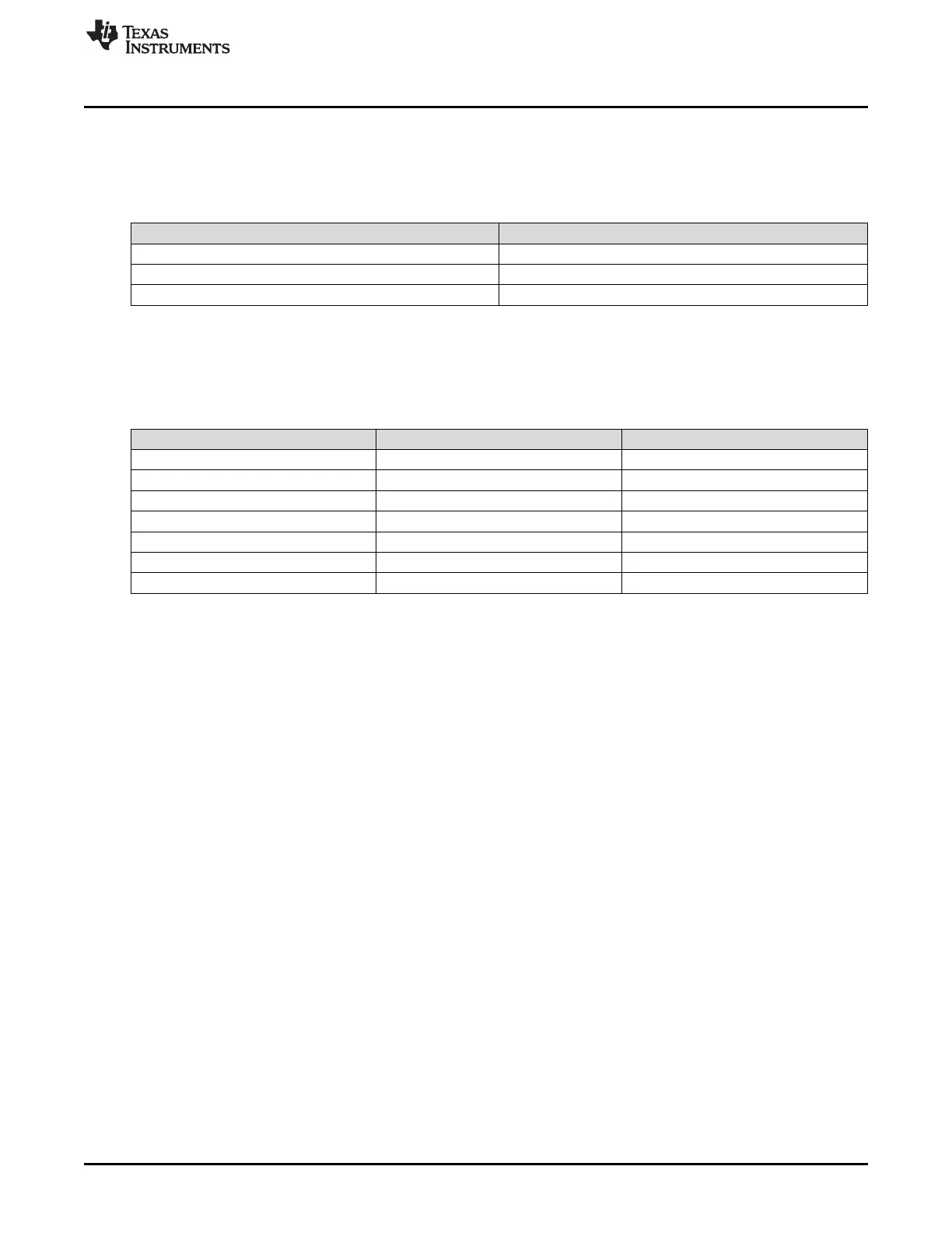
3.1.1 Push Buttons
There are three push buttons on the board connected, as described in Table 7. When a button is pressed,
the attached signal is pulled low; otherwise it is pulled high.
Table 7. Push Buttons
Switch Number Pin
S1 Reset
S2 GPIO2[4]
S3 GPIO2[5]
3.1.2 LEDs
There are seven LEDs on the board which function, as described in Table 8.
Table 8. LEDs
LED Signal Lit when...
D1 5V_IN 5 V is applied to J1
D2 VOLT_ERR Input voltage is > 5.8 V
D3 VCC_5VD_IN Board is powered from either J1 or USB
D4 GPIO6[13] Signal is high
D5 GPIO6[12] Signal is high
D6 GPIO2[12] Signal is high
D7 GPIO0[9] Signal is high
3.1.3 Power
The board can be powered with 5 V input through the J1 barrel connector.
3.1.4 USB-to-UART Port (J3)
The board features FD232 USB UART IC, which acts an external serial port. It is connected to the OMAP-
L138/C6748 UART2 peripheral.
Windows and Linux drivers for the chip can be found on the FTDI product page.
3.2 Setup the Out of the Box Demonstration on LCDK
The LCDK provides a quick start guide in the packaging that walks users through the hardware setup to
run the out of the box demonstration that is programed in the flash or on the SD card included in the kit.
Please follow the instruction in the quick start guide to setup the demonstration. The Quick start guide is
also available to access online on ti.com in URLs provided below:
• TMSLCDK6748 Quick Start Guide
• OMAP-L138 DSP+ARM9™ Development Kit (LCDK) Quick Start Guide

 Loading...


