Setting up the OMAP-L138/C6748 Development Kit (LCDK)
www.ti.com
6
SPRUIL2A–February 2019–Revised September 2019
Submit Documentation Feedback
Copyright © 2019, Texas Instruments Incorporated
OMAP-L138/C6748 Low-Cost Development Kit (LCDK)
3 Setting up the OMAP-L138/C6748 Development Kit (LCDK)
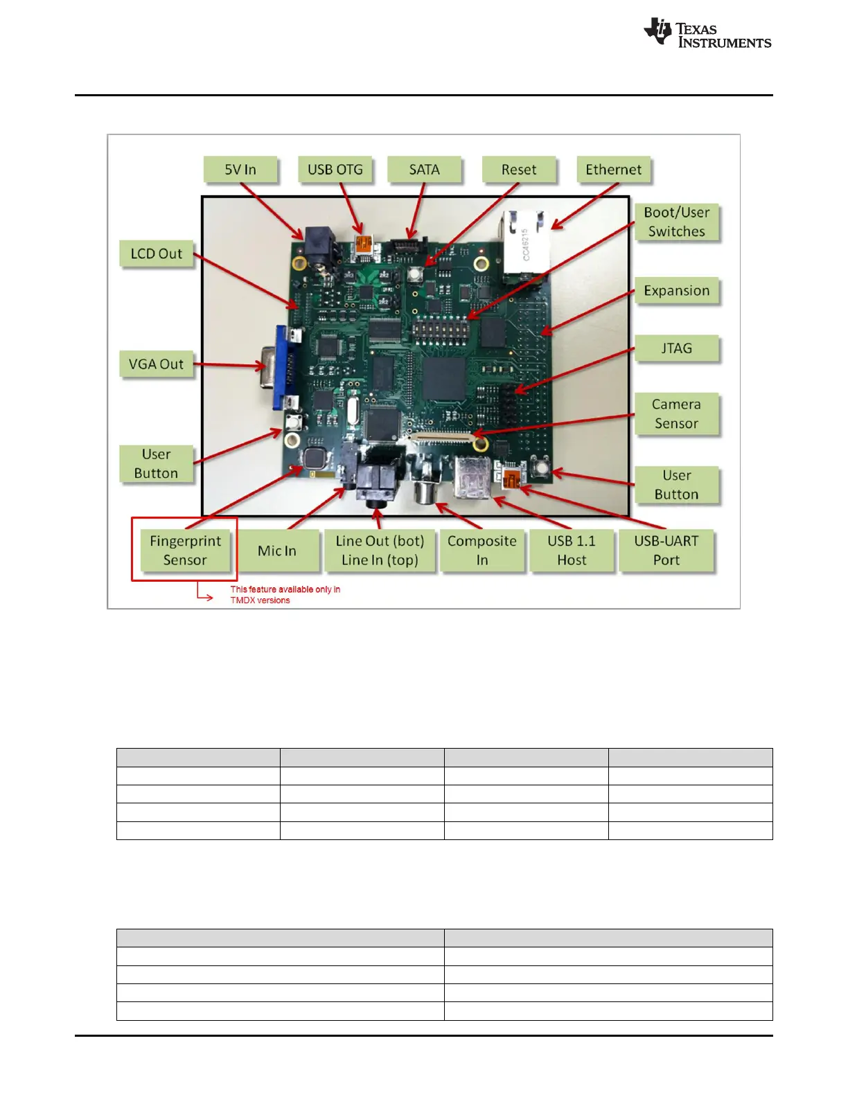
Figure 2. LCDK Hardware Features
3.1 User Interface
Switches 1-4 on SW1 are used to set the BOOT mode, as described in Table 5.
Table 5. Switches 1-4 on SW1
Switch Number UART2 NAND 16 MMC/SD0
1 OFF OFF OFF
2 ON ON OFF
3 OFF ON OFF
4 ON ON ON
Switches 5-8 on SW1 are user switches connected to GPIOs, as described in Table 6. When the switch is
ON, the pin is pulled low. When the switch is OFF, the pin is pulled high.
Table 6. Switches 5-8 on SW1
Switch Number Pin
5 GPIO0[1]
6 GPIO0[2]
7 GPIO0[3]
8 GPIO0[4]

 Loading...


