SCL
SDA
t
w(H)
t
w(L)
t
r
t
f
t
su1
t
h1
T0027-01
SCL
SDA
t
h2
t
(buf)
t
su2
t
su3
Start
Condition
Stop
Condition
T0028-01
TAS5707, TAS5707A
SLOS556B –NOVEMBER 2008–REVISED NOVEMBER 2009
www.ti.com
I
2
C SERIAL CONTROL PORT OPERATION
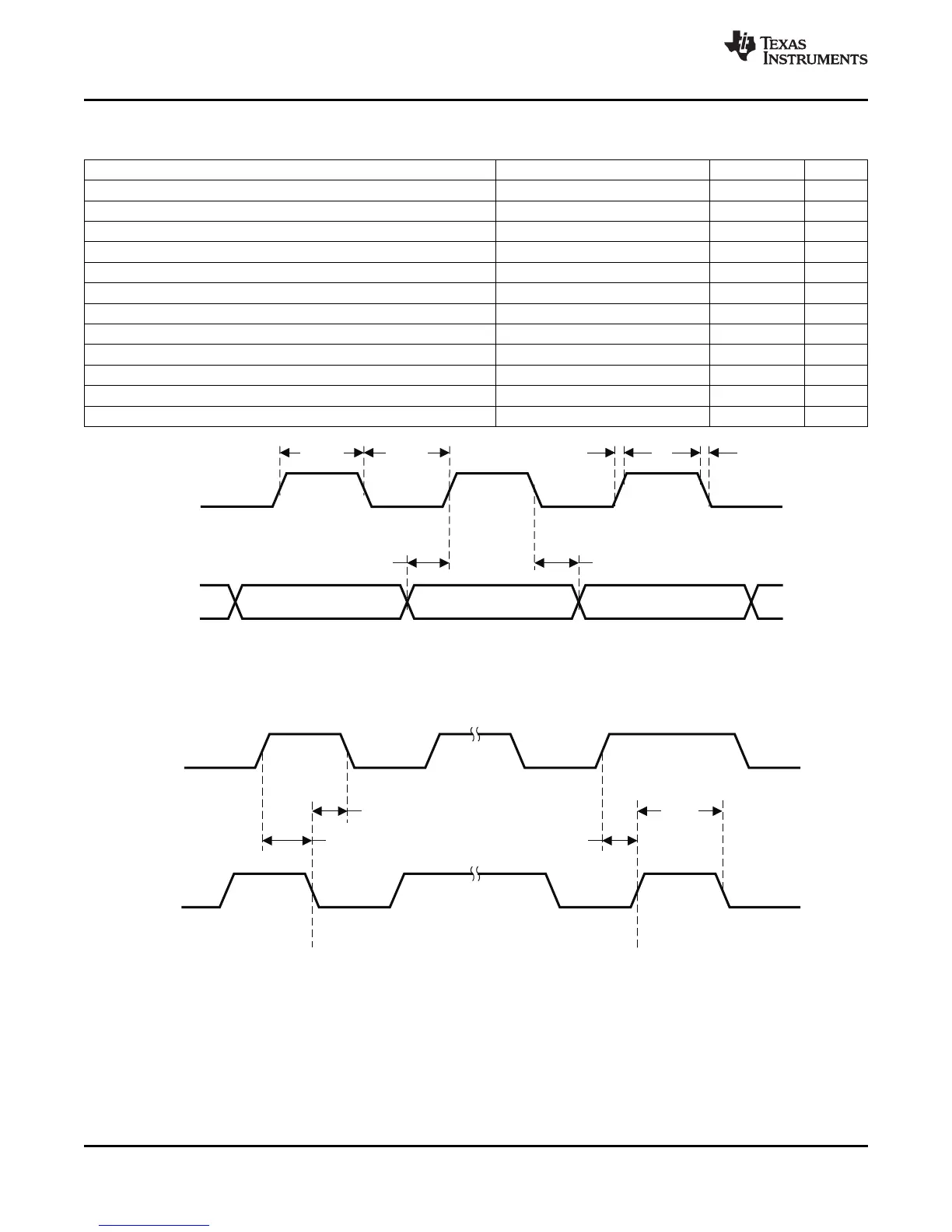
Timing characteristics for I
2
C Interface signals over recommended operating conditions (unless otherwise noted)
PARAMETER TEST CONDITIONS MIN MAX UNIT
f
SCL
Frequency, SCL No wait states 400 kHz
t
w(H)
Pulse duration, SCL high 0.6 μs
t
w(L)
Pulse duration, SCL low 1.3 μs
t
r
Rise time, SCL and SDA 300 ns
t
f
Fall time, SCL and SDA 300 ns
t
su1
Setup time, SDA to SCL 100 ns
t
h1
Hold time, SCL to SDA 0 ns
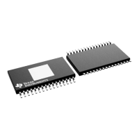
t
(buf)
Bus free time between stop and start condition 1.3 μs
t
su2
Setup time, SCL to start condition 0.6 μs
t
h2
Hold time, start condition to SCL 0.6 μs
t
su3
Setup time, SCL to stop condition 0.6 μs
C
L
Load capacitance for each bus line 400 pF
Figure 3. SCL and SDA Timing
Figure 4. Start and Stop Conditions Timing
12 Submit Documentation Feedback Copyright © 2008–2009, Texas Instruments Incorporated
Product Folder Link(s): TAS5707 TAS5707A