TAS5707, TAS5707A
SLOS556B –NOVEMBER 2008–REVISED NOVEMBER 2009
www.ti.com
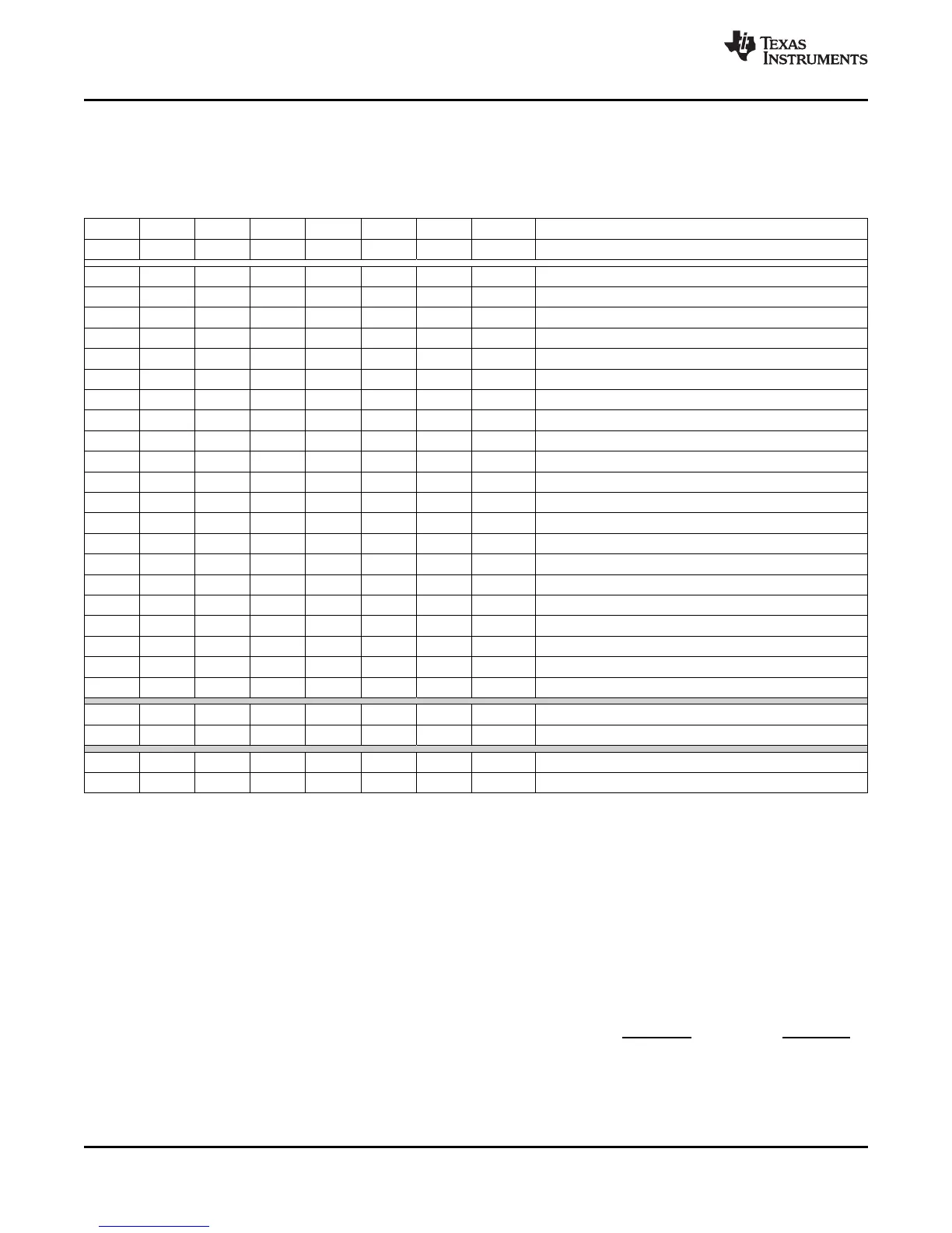
INPUT MULTIPLEXER REGISTER (0x20)
This register controls the modulation scheme (AD or BD mode) as well as the routing of I2S audio to the internal
channels.
Table 20. Input Multiplexer Register (0x20)
D31 D30 D29 D28 D27 D26 D25 D24 FUNCTION
0 0 0 0 0 0 0 0 Reserved
(1)
D23 D22 D21 D20 D19 D18 D17 D16 FUNCTION
0 – – – – – – – Channel-1 AD mode
1 – – – – – – – Channel-1 BD mode
– 0 0 0 – – – – SDIN-L to channel 1
(1)
– 0 0 1 – – – – SDIN-R to channel 1
– 0 1 0 – – – – Reserved
– 0 1 1 – – – – Reserved
– 1 0 0 – – – – Reserved
– 1 0 1 – – – – Reserved
– 1 1 0 – – – – Ground (0) to channel 1
– 1 1 1 – – – – Reserved
– – – – 0 – – – Channel 2 AD mode
– – – – 1 – – – Channel 2 BD mode
– – – – – 0 0 0 SDIN-L to channel 2
– – – – – 0 0 1 SDIN-R to channel 2
(1)
– – – – – 0 1 0 Reserved
– – – – – 0 1 1 Reserved
– – – – – 1 0 0 Reserved
– – – – – 1 0 1 Reserved
– – – – – 1 1 0 Ground (0) to channel 2
– – – – – 1 1 1 Reserved
D15 D14 D13 D12 D11 D10 D9 D8 FUNCTION
0 1 1 1 0 1 1 1 Reserved
(1)
D7 D6 D5 D4 D3 D2 D1 D0 FUNCTION
0 1 1 1 0 0 1 0 Reserved
(1)
(1) Default values are in bold.
PWM OUTPUT MUX REGISTER (0x25)
This DAP output mux selects which internal PWM channel is output to the external pins. Any channel can be
output to any external output pin.
Bits D21–D20: Selects which PWM channel is output to OUT_A
Bits D17–D16: Selects which PWM channel is output to OUT_B
Bits D13–D12: Selects which PWM channel is output to OUT_C
Bits D09–D08: Selects which PWM channel is output to OUT_D
Note that channels are enclosed so that channel 1 = 0x00, channel 2 = 0x01, channet 1 = 0x02, and channel 2 =
0x03.
46 Submit Documentation Feedback Copyright © 2008–2009, Texas Instruments Incorporated
Product Folder Link(s): TAS5707 TAS5707A