23
22
SCLK
32Clks
LRCLK
LeftChannel
24-BitMode
1
20-BitMode
16-BitMode
15
14
MSB LSB
SCLK
32Clks
RightChannel
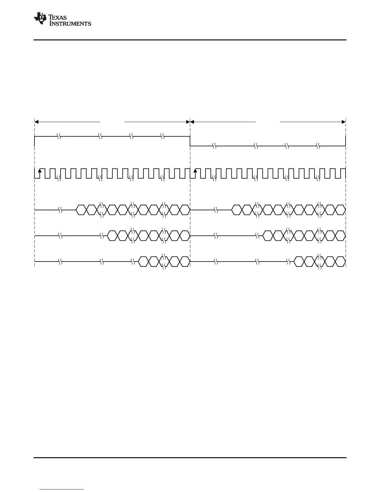
2-ChannelRight-Justified(SonyFormat)StereoInput
T0034-03
19 18
1
19 18
1
0
0
0
15
14
15
14
23
22 1
15
14
MSB LSB
19 18
1
19 18
1
0
0
0
15
14
15
14
TAS5707, TAS5707A
www.ti.com
SLOS556B –NOVEMBER 2008–REVISED NOVEMBER 2009
Right-Justified
Right-justified (RJ) timing uses LRCLK to define when the data being transmitted is for the left channel and when
it is for the right channel. LRCLK is high for the left channel and low for the right channel. A bit clock running at
32, 48, or 64 × f
S
is used to clock in the data. The first bit of data appears on the data 8 bit-clock periods (for
24-bit data) after LRCLK toggles. In RJ mode the LSB of data is always clocked by the last bit clock before
LRCLK transitions. The data is written MSB first and is valid on the rising edge of bit clock. The DAP masks
unused leading data bit positions.
Figure 23. Right Justified 64-f
S
Format
Copyright © 2008–2009, Texas Instruments Incorporated Submit Documentation Feedback 23
Product Folder Link(s): TAS5707 TAS5707A