Output Level (dB)
Input Level (dB)
T
O
K
M0091-02
1:1 TransferFunction
Implemented TransferFunction
S
Z
–1
AlphaFilterStructure
w
a
B0265-01
Energy
Filter
a w,
T,K,O a w
a
,
a d d
/ ,a w
DRC
0x3A 0x40,0x41,0x42 0x3B/0x3C
Compression
Control
Attack
and
Decay
Filters
AudioInput
DRCCoefficient
NOTE:
=1 –w a
TAS5707, TAS5707A
SLOS556B –NOVEMBER 2008–REVISED NOVEMBER 2009
www.ti.com
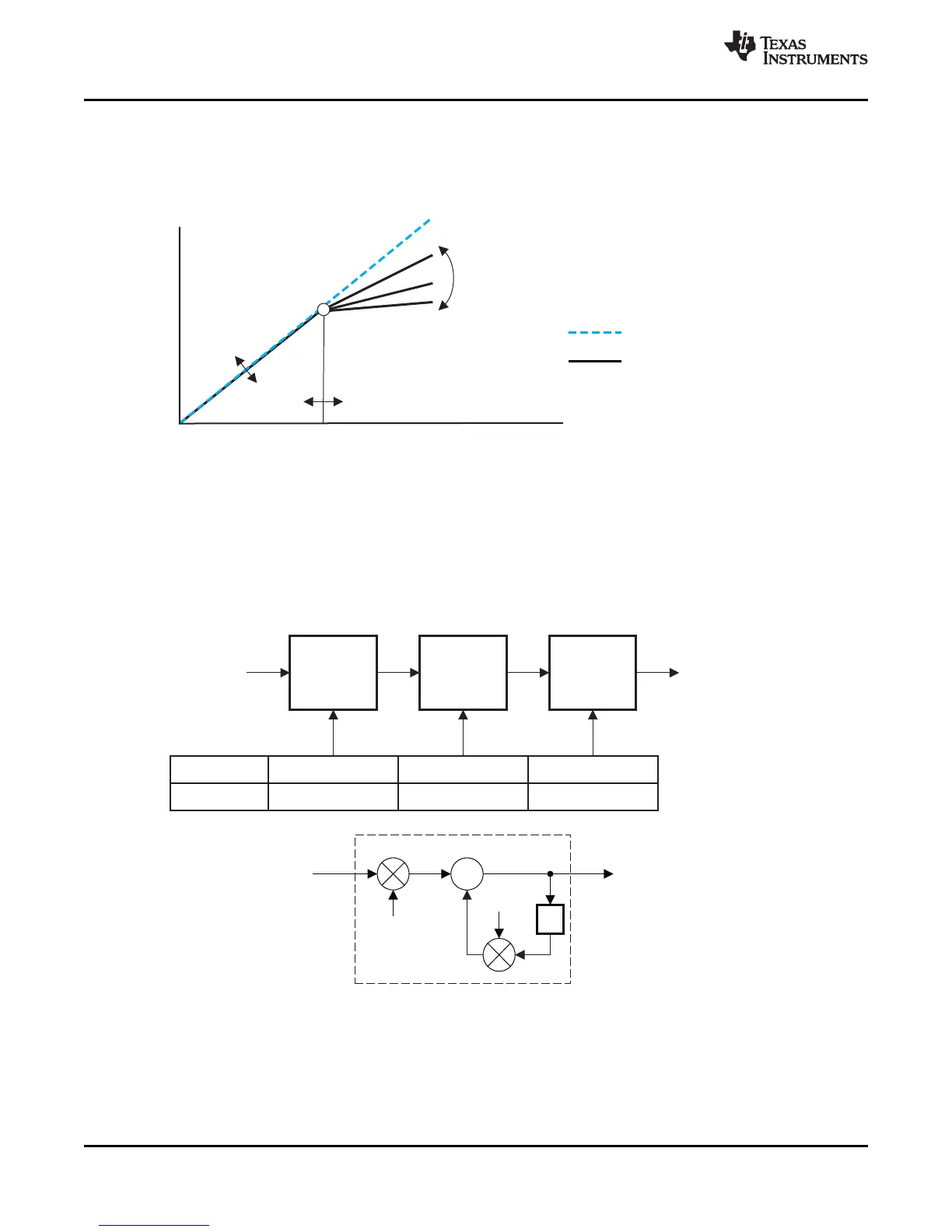
Dynamic Range Control (DRC)
The DRC scheme has a single threshold, offset, and slope (all programmable). There is one ganged DRC for the
left/right channels.
The DRC input/output diagram is shown in Figure 31.
Professional-quality dynamic range compression automatically adjusts volume to flatten volume level.
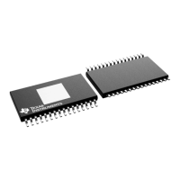
• One DRC for left/right
• The DRC has adjustable threshold, offset, and compression levels
• Programmable energy, attack, and decay time constants
• Transparent compression: compressors can attack fast enough to avoid apparent clipping before engaging,
and decay times can be set slow enough to avoid pumping.
Figure 31. Dynamic Range Control
Figure 32. DRC Structure
28 Submit Documentation Feedback Copyright © 2008–2009, Texas Instruments Incorporated
Product Folder Link(s): TAS5707 TAS5707A