Usage Notes and Known Design Exceptions to Functional Specifications
www.ti.com
8
SPRZ412K–December 2013–Revised February 2020
Submit Documentation Feedback
Copyright © 2013–2020, Texas Instruments Incorporated
TMS320F2837xD Dual-Core MCUs Silicon Revisions C, B, A, 0
Advisory Analog Bandgap References
Revision(s) Affected 0, A, B, C
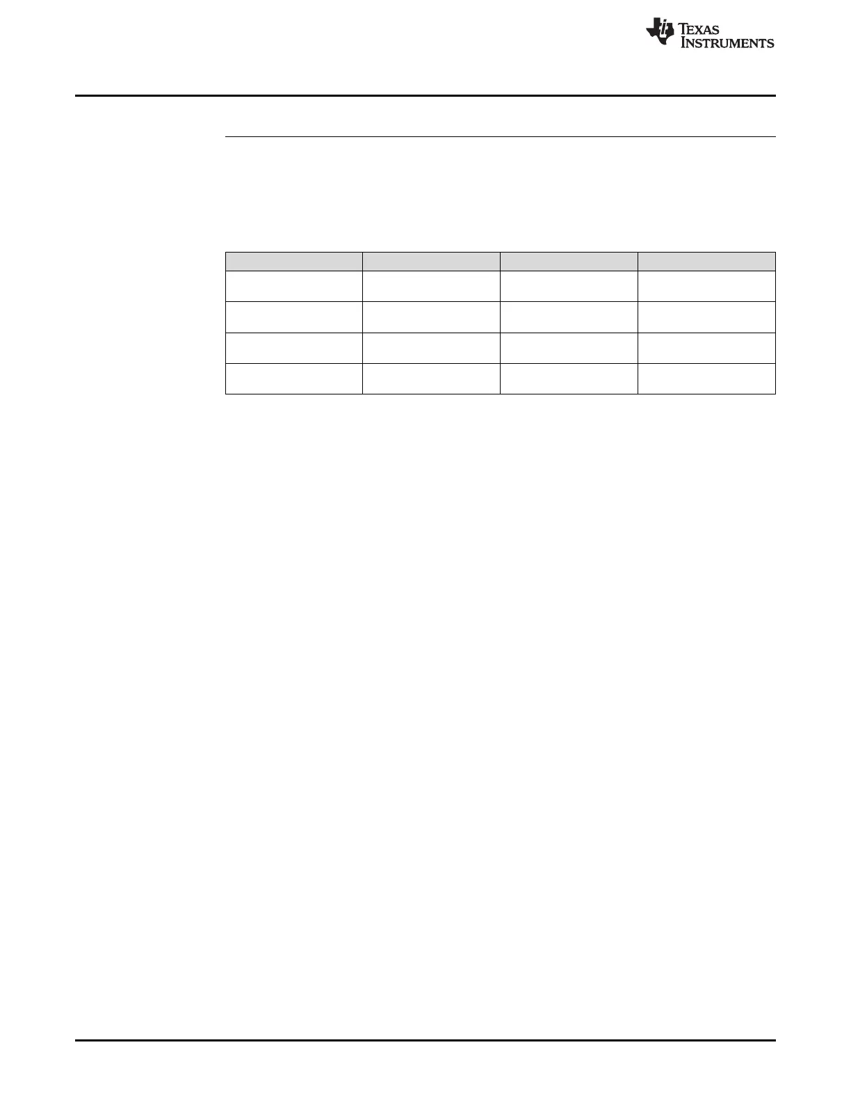
Details The Analog Subsystem includes internal bandgap reference circuits that are shared by
the embedded analog modules. Table 5 shows the bandgap usage by module.
Table 5. Bandgap Usage by Module
BANDGAP ADC BUFFERED DAC CMPSS
BGA ADCA DACA
DACB
CMPSS1
CMPSS2
BGB ADCB DACC CMPSS3
CMPSS4
BGC ADCC CMPSS5
CMPSS6
BGD ADCD CMPSS7
CMPSS8
Each bandgap reference—BGA, BGB, BGC, or BGD—will power up when one or more
of the dependent modules are enabled. An active bandgap reference will power down if
all dependent modules are disabled.
For example, bandgap B (BGB) is powered down unless one or more of the following
register bits are set:
• AdcbRegs.ADCCTL1.bit.ADCPWDNZ
• DaccRegs.DACOUTEN.bit.DACOUTEN
• Cmpss3Regs.COMPCTL.bit.COMPDACE
• Cmpss4Regs.COMPCTL.bit.COMPDACE
The CMPSS and GPDAC power-up time specification in the TMS320F2837xD Dual-
Core Microcontrollers Data Manual previously did not account for the bandgap power-up
time. This 10- µs value has been increased to 500 µs to account for the bandgap power-
up time.
Workaround(s) If your application was utilizing a power-up time of 10 µs for the CMPSS and GPDAC,
you do not need to increase it to 500 µs if the respective ADC on that bandgap was
turned on before the CMPSS and GPDAC, and the ADC power-up time of 500 µs was
adhered to.
For simplicity, it is recommended that 500 µs be used as the power-up time for both
CMPSS and GPDAC.
 Loading...


