Premier Elite 8XP Installation Manual
INS179-5 3
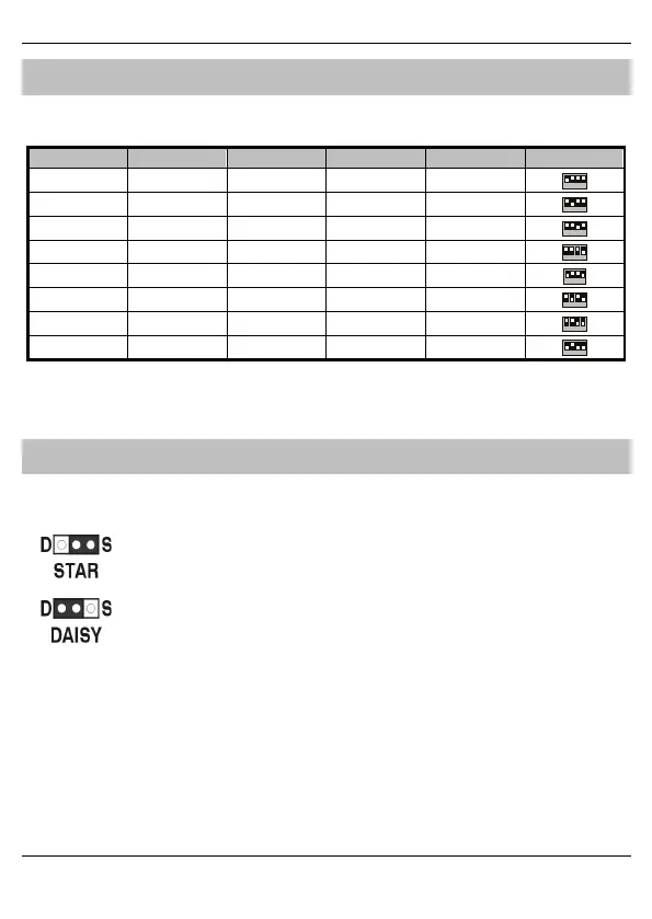
Selecting an Address
Each expander must be assigned a different address using the DIL switches located in the centre of
the PCB. The table below shows the expander addressing:
Address DIL 1 DIL 2 DIL 3 DIL 4
1 On or Off Off Off Off
2 Off On Off Off
3 Off Off On Off
4 Off Off Off
6 Off On Off On
7 Off Off On On
8 On Off On On
Never set two expanders on the same network to the same address.
Expanders are factory set to address 1.
Star and Daisy Jumper Option
The PCB has a jumper JP3 which allows you to select either STAR (S) or DAISY (D) wiring
configuration. The jumper should be set as follows:
If the network IN connection is wired in parallel with any other device the jumper
MUST be set to the S position. All previous versions of the expander operated in this
mode and for backward compatibility the unit is supplied with the jumper in this
position.
If the network IN connection is only wired to one device the jumper should be set to
the D position.
When the jumper is set to the STAR position the network data signals are not boosted between
expander and the previous device. In this mode the network cabling MUST not exceed 100m between
devices. When the jumper is set to the DAISY position the network data signals are boosted between
the expander and the previous device. This mode will allow expanders on the network to be connected
up to 250m apart and MUST only be selected if the expander has one device connected to the
network “IN” connections.