Do you have a question about the Texecom Premier Elite 8XP-W and is the answer not in the manual?
Describes mesh networking, signal routing, and self-healing properties.
Details panel firmware compatibility with expanders, listing legacy and Ricochet modes.
Discusses adding multiple expanders for flexibility and enhanced wireless capability.
Details maximum expanders, devices, and SmartKeys per control panel model.
Lists minimum requirements for advanced Ricochet MT2 functionality, including software versions.
Emphasizes treating each expander as a separate network and signal limitations.
Explains learning devices before final placement for correct registration and routing.
Advises learning SmartKeys after all devices/expanders are placed for critical system setup.
Details placing devices closest to the expander first and working outwards for optimal signal.
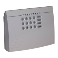
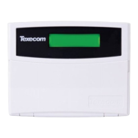
Explains connecting an engineer's keypad for programming and testing.
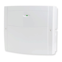
Describes the terminals for power (+/-) and data (T/R).
Details the serial port for connecting to a PC for monitoring software.
Explains tamper function enabling commission mode and attenuating signal.
Describes LED usage for programming devices directly to the receiver.
Specifies antenna count for different expander models.
Explains Green (data received) and Red (data transmitted) LEDs.
Indicates receiver functionality; steady flash means normal operation.
Used with programming LEDs to learn devices directly to the receiver.
Selects receiver functionality based on panel firmware, e.g., Legacy or Ricochet mode.
Assigns the receiver's address on the Premier network.
Flashes during transmitting or receiving RF data.
Disables lid and rear tamper functions.
Red LED flashes, increasing rate with data transmission.
For flashing the expander with updated firmware.
Details connecting the expander to the control panel using a 4-core cable for power and data.
Shows DIL switch settings for assigning expander addresses from 1 to 8.
Explains address range and slot usage for 32XP-W and 8XP-W expanders.
Illustrates expander addressing for a fully wireless system configuration.
Shows expander addressing for a mixed system with 32XP-W, 8XP-W, and 8XP.
Demonstrates expander addressing for a mixed system with 32XP-W and 8XP.
Specifies that only option switch 3 should be ON for Ricochet MT2 programming.
Details how to learn Ricochet devices via the Zone Setup menu.
Explains the procedure to delete devices from the expander.
Explains Always Awake, Auto, and Hybrid modes for device reporting.
Refers to other manuals for detailed programming of zone types and attributes.
Covers learning and managing SmartKey functionality via the "Setup Users" menu.
Explains selecting zones/expanders for SmartKey™ routing before learning.
Details how the "Route By" function selects zones for SmartKey™ routing.
Describes the process to remove a SmartKey™ from a user.
Provides a visual guide for learning the SmartKey™ and its settings.
Notes that only slots 1-8 are available for learning devices on 8XP-W.
Specifies option switch settings (1, 2, 4 OFF) for these firmware versions.
Details learning up to 32 wireless devices and SmartKey™ limitations.
Explains how signal strength is displayed and its range.
Visual guide for learning radio devices to the system.
Outlines the procedure to delete radio devices.
Sets switches 1, 2 & 3 ON for V7.00-V8.11 firmware.
Sets switches 2 & 3 ON for V8.11+ firmware.
States expander can be set to any valid address.
Lists LED indications for SmartKey™ status (Exit, Armed, etc.).
Explains learning devices via LED, Engineer's Keypad, or PC software.
All option switches 1, 2 & 4 should be OFF.
Expander should be set to address 1.
Steps to assign detectors to zones via engineer's mode.
Steps to assign detectors to zones via engineer's mode.
Steps to unassign a detector by programming its zone type as Null.
Explains assigning SmartKeys to available users on different control panels.
Lists available users for SmartKey™ assignment on different control panels.
Visual guide for assigning a SmartKey™ to a user.
Visual guide for removing a SmartKey™ assignment from a user.
Sets switches 1,2 & 3 ON for V10.95, and switches 2 & 3 ON for V10.96-V11.07.
Expander should be set to address 1.
States LED status cannot be obtained from the panel in these firmware versions.
Steps to assign detectors to zones for these legacy versions.
Steps to assign detectors to zones via engineer's mode.
Steps to unassign a detector by programming its zone type as Null.
Lists available users for SmartKey™ assignment on different control panels.
Visual guide for assigning a SmartKey™ to a user.
Visual guide for removing a SmartKey™ assignment from a user.
Notes direct learning is only available in legacy mode, using factory defaults.
Describes pressing the learn switch on the receiver and observing LED sequences.
Explains flashing LEDs indicate free slots; solid LEDs indicate occupied slots.
Notes learning & deleting devices is only available in Legacy Mode.
Visual guide for adding devices using the engineer's keypad.
Visual guide for deleting devices using the engineer's keypad.
Notes attribute changes are not available on Ricochet MT2 systems.
Explains saving changes via Yes key or scrolling through devices.
Visual guide for changing device attributes like Auto Mode or Always Awake.
Notes attribute changes are not available on Ricochet MT2 systems.
Explains saving changes via Yes key or scrolling through devices.
Attributes update on next power-up; immediate update via "Update Devices".
Describes how pressing Area key shows routing and signal strength in Commission Mode.
Shows examples of device routing with no hops, 1 hop, and 2 hops.
Used to immediately update device attributes (not SmartKey™) from Device List menu.
Describes what happens if the broadcast message fails and troubleshooting.
Explains how to start/stop Walktest mode via Panel, Keypad, or Monitor.
Notes LEDs enabled, response time reduced to 10s, lasts for 1 hour.
Describes failure scenarios and troubleshooting for walktest broadcast message.
Defines Sys: OK, V: version, JAM, CM, Nw, RIC, LEG indicators.
Shows how system status is displayed and options for viewing.
Warns not to use the Erase All function on Ricochet MT2 systems.
Explains codes like Ft, Rt, Act, R, 1, 2, S for device status.
Explains messages like Low Bat, No Info, Dev Flt, Ud Attr, Poll Error.
Lists information available for devices: Routeing, RSSI, Alarms, Visibility, Time since message.
Lists information available for SmartKey™: Routeing, RSSI, Button, Status.
Explains how to read routeing information, including question marks.
Explains how to read RSSI levels and the meaning of question marks.
Explains messages like "Not Ricochet", "No ms9 recvd yet", ">1hr since ms9".
Shows information relating to signal security on 8XP-W and 32XP-W.
Explains codes like 'a', 'S', 'p', 'd', 't' for device status.
Explains messages for no association, not connected, logon, and button presses.
Warns about using "Erase unknown keyfobs" and its limitations.
Ensures secure communications, attenuates RF signal, and sets devices to poll every 4 mins.
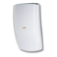
Explains device entering commission mode via tamper and LED indication of success/failure.
Refers to device manual for settings and mounting height.
Refers to device manual for sensitivity and placement.
Details additional inputs and their behavior when wired.
Explains Switch 3 function for MAG 2/COM reporting (tamper/alarm).
Explains how to start/stop Walktest mode via Panel, Keypad, or Monitor.
Explains polling occurs every 15 mins (4 mins in Commission Mode) for battery conservation.
Default for XT-W/QD-W on V1 systems; polls every 15 mins.
For devices needing constant signaling; default for Impaq Contact-W/Plus-W.
Devices sleep when set, wake on arming; default for XT-W/QD-W/DT-W in MT2.
States these modes are for future use.
Notes impact of Always Awake mode on battery life.
Details the four colors of the status LED and their meanings.
PA activation is enabled by default; panel programming required for Radio PA.
How to enable/disable alarm status LEDs via Keypad or Monitor.
How to activate auxiliary devices using SmartKey™ function keys.
Disarms system/areas without powering up SmartKey™, shows LED state change.
How alarm status LEDs indicate system status across multiple areas.
Explains how three alarm status LEDs flash to indicate an arm failure.
Factors affecting battery life: complexity, hops, Always Awake mode.
SmartKey™ battery life, non-replaceability, and replacement procedure.
Devices transmit warning when three months of battery remain.
Recommends checking for low battery warnings at service intervals or annually.
Explains devices enter "Offline" mode on power loss; recovery process.
Lists operating voltage, current consumption, and network cable details.
Provides dimensions and packed weight.
Details frequency, receiver type, and transmitter duty cycle.
Lists CE, WEEE, and RoHS directive compliance.
Table showing compliance with various EN standards for different products.
Lists product types (GCA1000-2, GCA2000) and their frequencies.
Details the two-year warranty against defects and limitations.
| Type | Wireless Expander |
|---|---|
| Zones | 8 |
| Wired Zones | 8 |
| Operating Temperature | -10°C to +55°C |
| Compatible with | Premier Elite Series |
| Keypad | No |
| Communication | Wireless |
| Power Supply | 12V DC |
| Battery Backup | Yes |
| Humidity | 95% non-condensing |