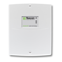
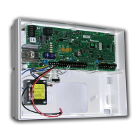
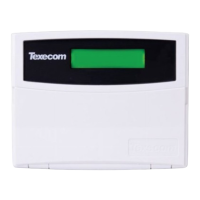
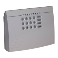
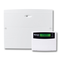
Premier Elite 8XP-W & 32XP-W Installation Manual
12 INS467-4
The networks are made up of four terminals incorporating power and data. To ensure correct
operation, all four terminals on the device must be connected to the corresponding terminals on the
control panel or previous device.
Expanders can be connected using 4-core cable. However, it is recommended that 6 or 8-core cable
is used as the spare cores can be used to ‘Double Up’ on the power connections if needed.
Standard 7/0.2 alarm cable can be used for most installations. However, under certain conditions it may be
necessary to use screened cable.
Selecting an Address
Each expander must be assigned a different address using the DIL switches located on the PCB.
The table below shows the expander addressing:
Address DIL 1 DIL 2 DIL 3 DIL 4
Never set two expanders on the same network to the same address. Expanders are factory set to address 1.On
legacy panels the expander will occupy 1 x Expander slot on the control panel, as well as the Network Receiver
slot.
Ricochet MT2 Expander Addressing
Introduction
The address range and switch position will depend on which combination of expanders are being
used. Each 32XP-W takes up 4 address slots on the control panel network, however the network
slots are virtual until devices are assigned to available zones. It is possible that if a 32XP-W is being
used at Address 1, but only 16 devices have been used, Address 3 & 4 are available for hardwired
8XP's or 8XP-W's.
Please see some examples of mixing different types of Expanders on various Elite panels and the
addressing requirements.
 Loading...
