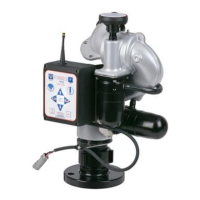
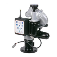
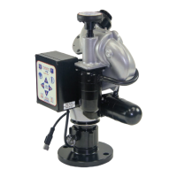
13
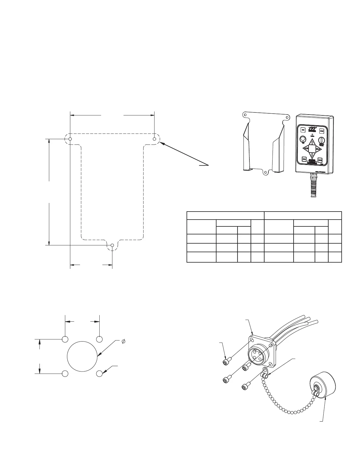
5.2.1 HOLSTER MOUNTING
Select proper location for mounting holster, preferably inside a storage compartment. Panel space required will be 6.5” x 8.0” (165 x
203mm). Refer to Figure 5.2.1for hole dimensions. Holster can be used as template.
Fig 5.2.1 Tether Operator Station Holster Hole Dimensions
Material Use Material Use
Thickness Drill Thickness Drill
5/64-3/32 .206 5.2 #5 3/32 .213 5.4 #3
1/8 .213 5.4 #3 1/8 .221 5.6 #2
3/16 .221 5.6 #2 3/16 .228 5.8 #1
Inches mm Inches mm
ALUMINUM STEEL
Hole Size Chart For Self Tapping Screws
Hole Size Hole Size
5 3/4"
(146 mm)
2 7/8"
(73 mm)
7 1/4"
(184 mm)
5.2.2 RECEPTACLE MOUNTING
Select proper location for mounting receptacle. Receptacle is 1-1/4” x 1-1/4” and ½” deep. (32 mm x 32 mm x 13 mm) Allow extra room
behind receptacle for wires. Refer to Figure 5.2.2 for hole dimensions.
Fig 5.2.2
Tether Operator Station
Receptacle Hole Dimensions
Drill (4) .098”
(#40) Holes
7/8”
(22 mm)
7/8”
(22 mm)
25/32”
(20 mm)
HOLE LAYOUT
MOUNT RECEPTACLE WITH
#4 SELF-TAPPING SCREWS.
TIGHTEN SECURELY.
INSTALL
CHAIN CONNECTOR
UNDER SCREW HEAD
Y5310 TETHER RECEPTACLE
Y5320 CLOSURE CAP
5.2.3 ELECTRICAL WIRING
See figure 5.0 for typical connections. The 4-conductor cable from the receptacle needs to be connected to power (red & black) and to
the communication link (blue & white) from the monitor. Refer to Figure 5.1.2 for typical cable preparation.
Drill (3) Pilot Holes
(refer to hole size chart)
Mount Holster With (3)
1/4-20 Self-Tapping Screws.
Tighten Securely.
This operator station will have a factory installed 4-conductor cable, which will act as a tether, with a plug on the end. The installer will
need to mount the holster and receptacle.
The holster is supplied with(3) 1/4-20 stainless steel self-tapping screws. Make sure the material beneath the bracket is substantial and
thick enough to hold self-tapping screws. Make sure the area on the back side of the mounting surface is clear of obstructions. We
recommend a minimum thickness of 3/32" (.093" - 2.4 mm) in aluminum and 5/64 (.078"-2mm) in steel See the chart in Figure 5.2.1 to
determine the correct pilot hole size.
5.2 TETHER MONITOR OPERATOR STATION (Y4E-CT-##)