14
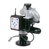
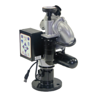
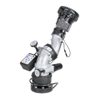
5.3 WIRELESS MONITOR OPERATOR STATION (YE-RF-##)
The storage bracket is supplied with (3) 1/4-20 stainless steel self-tapping screws. Make sure the material beneath the bracket is
substantial and thick enough to hold self-tapping screws. Make sure the area on the backside of the mounting surface is clear of
obstructions. We recommend a minimum thickness of 3/32" (.093" - 2.4 mm) in aluminum and 5/64 (.078"-2mm) in steel. See the chart
in Figure 5.3.1 to determine the correct pilot hole size.
Select proper location for mounting storage bracket. Panel space required will be 6.0“ x 11.2“ (152 x 285mm). Refer to Figure 5.3.1 for
hole dimensions. Bracket can be used as a template. Be sure spring is in position.
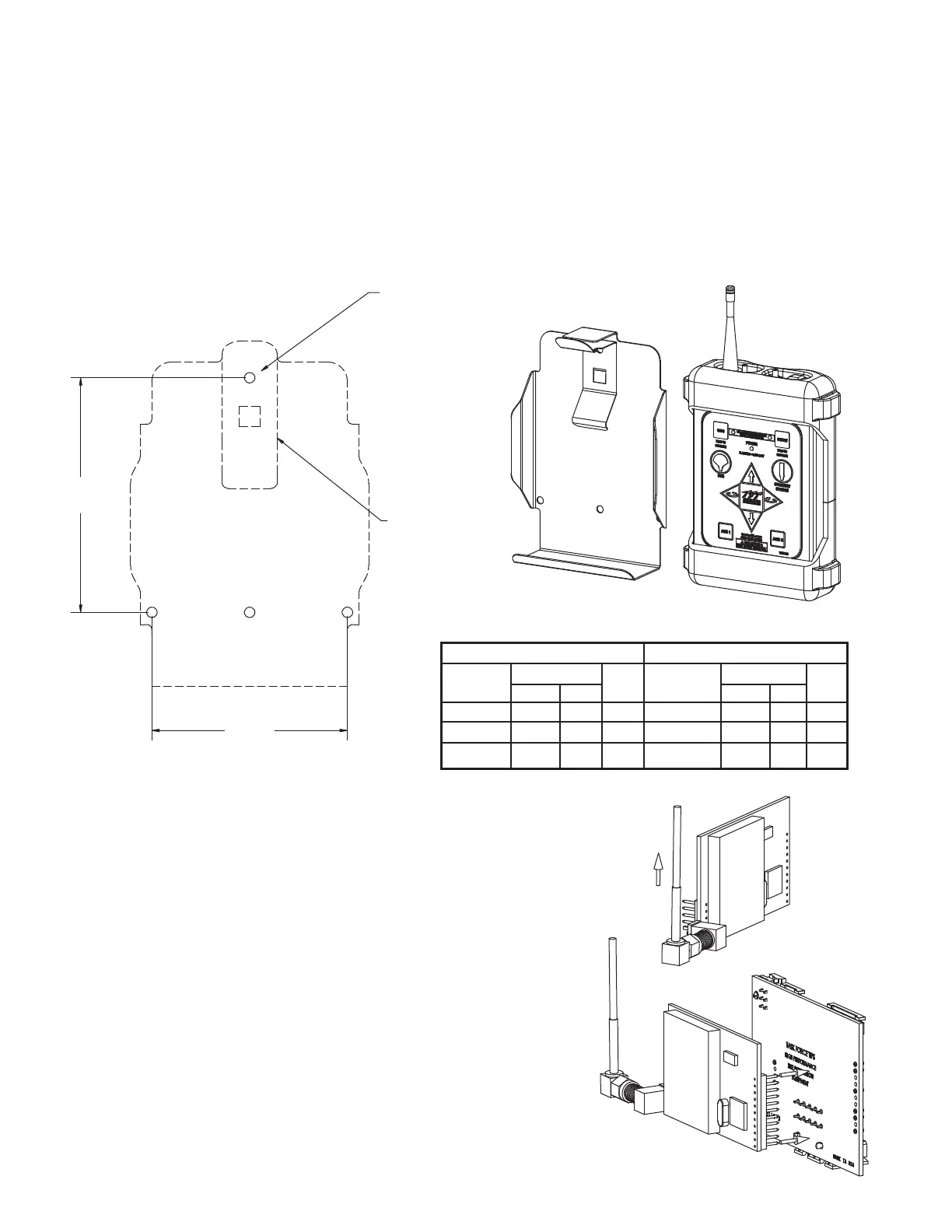
5.3.1 MOUNTING STORAGE BRACKET
Fig 5.3.1 Wireless Operator Station
Storage Bracket Hole Dimensions
Material Hole Size Use Material Hole Size Use
Thickness Inches mm Drill Thickness Inches mm Drill
5/64-3/32 .206 5.2 #5 3/32 .213 5.4 #3
1/8 .213 5.4 #3 1/8 .221 5.6 #2
3/16 .221 5.6 #2 3/16 .228 5.8 #1
ALUMINUM STEEL
Hole Size Chart For Self Tapping Screws
5"
[127mm]
6"
[152mm]
Drill (3) Pilot Holes
(refer to hole size chart)
Mount Bracket with (3)
1/4-20 Self-Tapping Screws.
Tighten Securely.
Spring
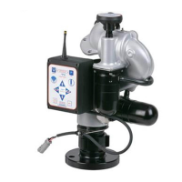
5.3.2 INSTALLING RADIO
1) Turn off power and remove lid from monitor control box. Be careful
to open lid slowly as lid will be connected to communication board
by a flat cable.
2) Unplug connector with blue & white wires and remove the small
communication board on the far left.
3) Attach antenna connector to radio board with the cable in the
orientation. (Fig 5.3.2a) Note, in some RC monitors, cable tie may
need to be cut to attach antenna.
4) Plug radio board into communication board. (Fig 5.3.2b) Be careful
to line up pins.
5) Plug communication board/radio board into main board. Press
down to seat securely.
6) Insert connector with blue & white wires into communication board.
7) Replace lid onto box. Be sure to guide flat cable down onto motor
boards and to not pinch any wires between lid and box.
8) Tighten lid screws equally in a criss-cross pattern.
The YE-RF-## Wireless Operator Station is supplied with a radio board that needs to be installed in the monitor control box and a
storage bracket.
Fig 5.3.2a
Fig 5.3.2b