EasyManua.ls Logo

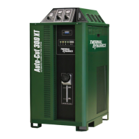
Thermal Dynamics AUTO-CUT 300 XT User Manual

Thermal Dynamics AUTO-CUT 300 XT
162 pages
To Next Page IconTo Next Page
Page #1 background imageLoading...
Page #1 background image
ThermalDynamics.com
480V
®
AUTO-CUT 300 XT
PLASMA CUTTING SYSTEM
Operating
Manual
Revision: AE Issue Date: May 27, 2015 Manual No.: 0-5300

Table of Contents

Questions and Answers:

Thermal Dynamics AUTO-CUT 300 XT Specifications

General IconGeneral
Open Circuit Voltage (OCV)300 VDC
Operating Temperature14°F to 104°F (-10°C to 40°C)
Output Current30A
Duty Cycle60% @ 100 A
Cutting Capacity (Recommended)3/8 in (10 mm)
Cutting Capacity (Maximum)1-1/4 in (32mm)
Pierce Capacity3/8 in (10 mm)
Cutting Capacity1-1/4 in (32mm)
Gas SupplyCompressed Air or Nitrogen
Gas Flow5.3 cfm (150 lpm)
Gas TypeCompressed Air or Nitrogen

Summary

SECTION 1: SAFETY

Safety Precautions - ENGLISH

Summarizes precautionary information from references for installation and operation.

Précautions de sécurité - FRENCH CANADIAN

Summarizes precautionary information in French for installation and operation.

SECTION 2: SPECIFICATIONS

Power Supply Specifications & Electrical Requirements

Details technical specifications, duty cycle, operating range, and electrical input requirements.

Gas Requirements

Lists required gases, quality, pressure, flow, and quality specifications.

XT-301 Torch Specifications

Provides dimensions, lead lengths, and part details for the XT-301 Torch.

SECTION 3: INSTALLATION

Installation Requirements

Outlines requirements for electrical supply, gas supply, and cooling system setup.

Cables and Leads Identification

Provides a diagram identifying system cables and their connections.

Cables & Leads Identification

Details specific cable types, colors, and their connections.

Connect Input Power and Ground Cables

Step-by-step guide for connecting primary input power and system ground cables.

Ground Connections

Detailed procedures for creating earth grounds and minimizing EMI.

Set Switches on the Command - Control Module

Details on configuring switches on the Command-Control Module for operation.

Voltage Divider for iHC Torch Height Control

Instructions for installing the Voltage Divider board for iHC height control.

Fill Cooling System

Procedure for filling the coolant tank and checking the system.

SECTION 4: OPERATION

System Operation

Step-by-step guide for starting up and operating the plasma cutting system.

Power Supply Status Codes

Lists and explains status codes indicating system conditions or faults.

SECTION 5: MAINTENANCE

General Maintenance

Provides a periodic maintenance schedule for the power supply.

Arc Starter Service

Troubleshooting chart for common arc starter issues and their remedies.

SECTION 6: REPLACEMENT ASSEMBLIES & PARTS

SECTION 7: TORCH MAINTENANCE

APPENDIX 1: CNC Control Module

APPENDIX 17: Advanced Troubleshooting

101 Plasma Enable Is Disabled

Explains code 101 and its causes related to plasma enable settings.

102 Pilot Ignition Failure

Details code 102 and common causes for pilot ignition failure.

201 Missing AC Phase

Explains code 201 and troubleshooting steps for missing AC phases.

401 Coolant Level Low

Explains code 401 and troubleshooting for low coolant level.

501 CANBUS Failure to Acknowledge Fault

Explains code 501 and troubleshooting for CANBUS failure to acknowledge.

612 USB Port Power Fault

Explains code 612 and troubleshooting for USB port power faults.

Related product manuals