Do you have a question about the Thermal Dynamics CUTMASTER A40 and is the answer not in the manual?
Crucial safety guidelines for operating and maintaining plasma arc equipment, covering electrical shock, fumes, and fire hazards.
Explanation of symbols used for notes, cautions, and warnings to highlight important information and potential hazards.
Statement confirming equipment compliance with applicable EU directives and national legislation for safety and EMC.
Details the limited warranty period for CUTMASTER™ plasma cutting systems and exclusions.
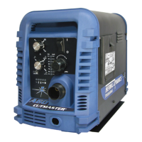
Technical specifications for the CUTMASTER A40 power supply, including input power, output current, and duty cycle ratings.
Requirements for input voltage, frequency, power, and suggested circuit protection for wiring the power supply.
Details torch configurations, lead lengths, parts, gas requirements, and torch ratings.
Guidelines for selecting a suitable location and securely mounting the power supply unit.
Instructions for connecting the primary input power, including cover removal and phase wiring.
Procedure for connecting the gas supply to the unit, including optional filter installation.
Steps for connecting the torch lead to the power supply unit, ensuring proper connection.
Instructions for mounting and aligning the torch assembly for automated or machine cutting.
Description and function of the controls and indicators on the front panel of the power supply.
Steps to take before starting each operating session, including torch parts, connections, and power.
Procedures for operating machine and automated torches, including positioning and travel speed.
Detailed instructions for hand torch operation, including standoff and drag cutting techniques.
Tables providing recommended cutting speeds, gas pressure, and voltage for various material thicknesses.
Routine maintenance tasks for the power supply, categorized by frequency of use (each use, weekly, 3 months, 6 months).
Lists common problems, their symptoms, and possible causes related to the plasma cutting system.
A guide to diagnose and resolve common issues based on problem symptoms and indicator lights.
Procedures for inspecting and replacing wear items such as shield cups, tips, electrodes, and starter cartridges.
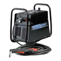
Catalog numbers for replacement power supply units and included accessories.
List of replacement parts for the SL100SV automated plasma cutting torch assembly.
Breakdown of consumable parts for the SL60 manual plasma cutting torch.
Visual representation of the system's operational sequence and logic flow.
Detailed electrical schematic for 208V and 460V units, illustrating component connections and layout.
Record of manual revisions, including dates, revision codes, and changes made in each version.
| Brand | Thermal Dynamics |
|---|---|
| Model | CUTMASTER A40 |
| Category | Welding System |
| Language | English |


