INSTALLATION PROCEDURES 3-4 Manual 0-2859
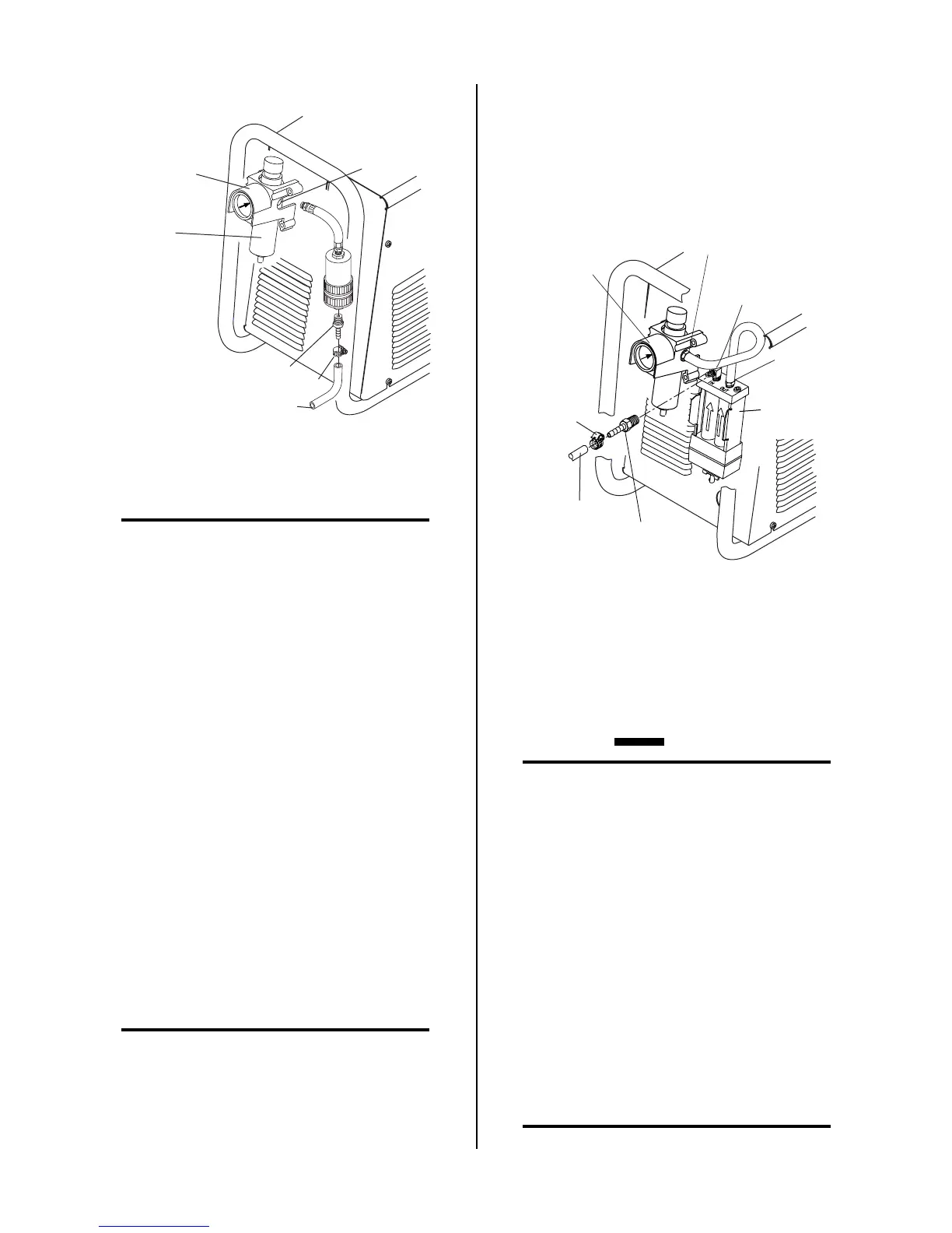
Art # A-03000
Regulator/Filter
Assembly
Inlet Port
Bowl
1/4 NPT Hose Fitting
1/4" (6 mm) Gas Supply Hose
Hose Clamp
Optional Single-Stage Filter Installation
NOTE
For a secure seal, apply thread sealant to the fitting
threads, according to manufacturer's instructions.
Do Not use Teflon tape as a thread sealer as small
particles of the tape may break off and block the
small gas passages in the torch. Connect the gas
supply as follows:
a. Attach the Single-Stage Filter Hose to the Regu-
lator/Filter Assembly inlet port as shown.
b. Attach the Single-Stage Filter Assembly to the
filter hose.
c. Use customer-supplied fittings to connect the
gas line to the Filter. A 1/4 NPT to 1/4" hose
barbed fitting is shown as an example.
2. Optional Two-Stage Air Filter Kit
This optional two-stage air line filter is also for use
on compressed air shop systems. Filter removes mois-
ture and contaminants to at least 5 microns.
Connect the gas supply as follows:
a. Attach the Two Stage Filter bracket to the back
of the power supply per instructions supplied
with the filter assembly.
NOTE
For a secure seal, apply thread sealant to the fit-
ting threads according to manufacturer's instruc-
tions. Do Not use Teflon tape as a thread sealer as
small particles of the tape may break off and block
the small gas passages in the torch.
b. Connect the two stage filter outlet hose to the
inlet port of the Regulator/Filter Assembly.
c. Use customer-supplied fittings to connect the
gas line to the Filter. A 1/4 NPT to 1/4" hose
barbed fitting is shown as an example.
Art # A-03004
Regulator/Filter
Assembly
Hose
Clamp
1/4 NPT
Hose Fitting
1/4" (6 mm) Gas
Supply Hose)
2-Stage Filter
Inlet Port (IN)
Outlet Port
(OUT)
Regulator Inlet Port
Two Stage
Filter
Assembly
Optional Two-Stage Filter Installation
E. Using High Pressure Gas Cylinders
Refer to the following when using high pressure gas cyl-
inders as the gas supply:
CAUTION
Pressure should be set at 100 psi (6.9 bar) at the
high pressure gas cylinder regulator.
1. Refer to the manufacturer’s specifications for in-
stallation and maintenance procedures for high
pressure gas regulators.
2. Examine the cylinder valves to be sure they are
clean and free of oil, grease or any foreign mate-
rial. Momentarily open each cylinder valve to
blow out any dust which may be present.
3. The cylinder must be equipped with an adjust-
able high-pressure regulator capable of outlet
pressures up to 100 psi (6.9 bar) maximum and
flows of up to 400 scfh (190 lpm).
4. Use customer-supplied fittings to connect the gas
line to the cylinder.
NOTE
Supply hose must be at least 1/4 inch (6 mm) I.D.