Manual 0-2859 5-5 CUSTOMER/OPERATOR SERVICE
2. Gas supply pressure too high
a. Maximum 125 psi (8.6 bar) inlet pressure
3. Shield Cup not properly installed.
a. Check to see that Control Circuit (PIP) pins are
installed. Refer to the torch manual for details.
4. Faulty components in unit
a. Return for repair or have qualified technician
repair per Service Manual.
J. Torch cuts but not adequately
1. Current set too low
a. Increase current setting.
2. Torch is being moved too fast across workpiece
a. Reduce cutting speed (refer to Torch Instruction
Manual supplied with torch).
3. Excessive oil or moisture in torch
a. Hold torch 1/8 inch (3 mm) from clean surface
while purging and observe oil or moisture
buildup (do not activate torch).
4. Torch tip being dragged on work.
a. Lift torch tip off work. At output settings over
40 amps, control circuitry automatically reduces
output current to 40 amps if the torch tip con-
tacts the workpiece.
5.05 Power Supply Basic Parts
Replacement
WARNING
Disconnect primary power to the system before dis-
assembling the torch, leads, or power supply.
This section describes procedures for basic parts replace-
ment. For more detailed parts replacement procedures,
refer to the Power Supply Service Manual.
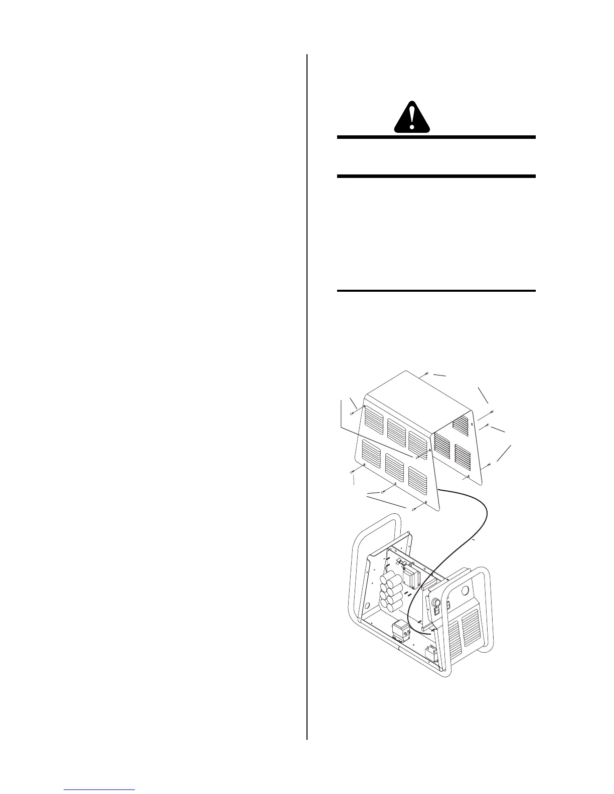
A. Cover Removal
1. Remove the upper screws which secure the cover
to the main assembly.
NOTE
There is a ground wire connection to the inside of
the unit. There is no need to disconnect the ground
wire, unless there is a need for more room to work.
A-03001
Lower
screws
Upper screws
Ground wire
Lower
screws
Upper
screws
Cover Removal