CUSTOMER/OPERATOR SERVICE 5-6 Manual 0-2859
2. Loosen, but do not remove, the lower screws, then
carefully pull the Cover up and away from the unit
to gain access to the inside of the unit.
3. Reinstall the cover as follows:
a. Reconnect the ground wire, if necessary.
b. Place the cover onto the frame so that it rests on
the lower screws.
c. Reinstall and tighten the upper screws.
d. Tighten lower screws.
B. Fuse Replacement
1. Remove the unit cover per paragraph "A" above.
2. Locate the internal fuse on the left side of the center
chassis.
3. Replace the fuse. A replacement fuse is located in-
side the power supply. Refer to Section 6, Parts
Lists, for replacement fuse catalog number.
4. Reinstall the cover by reversing the steps in para-
graph "A" above.
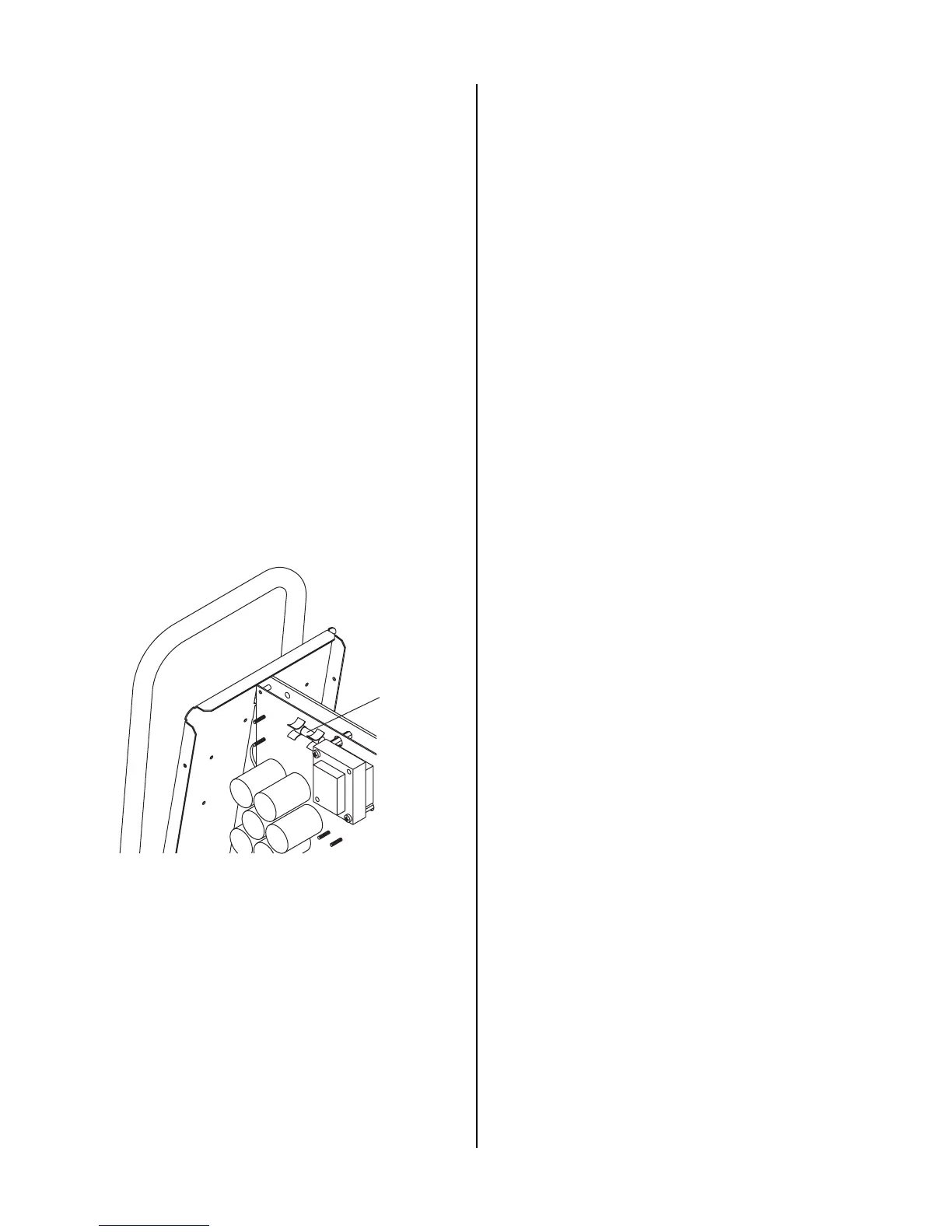
Art # A-03002
Fuse Location
Internal Fuse Location
This completes the parts replacement procedures.