OPERATION 4-2 Manual 0-2859
C. Rear Panel Features
1. Gas Input Port
Input connection for compressed air.
WARNING
This unit is not to be used with oxygen (O
2
).
A-02996
1
2
3
Rear Panel Features
2. Primary Input Power Cable
Primary input power cable (400-V, 460-V and 600-Volt
units); input power cable with plug on 208/230-Volt
units.
3. Gas Pressure Regulator / Filter Assembly
Pressure regulator to adjust the input gas pressure to
the Power Supply. The pressure regulator includes a
built-in filter. For improved filtering, other filtering
packages are available as options.
4.03 Preparations For Operating
Follow this procedure at the beginning of each shift:
WARNING
Disconnect primary power at the source before as-
sembling or disassembling power supply, torch
parts, or torch and leads assemblies.
A. Torch Parts Selection
Check the torch for proper assembly and appropriate
front end torch parts. The torch parts must correspond
with the type of operation (cutting or gouging). Re-
fer to the torch manual for proper parts selection.
B. Check Primary Input Power Source
1. Check the power source for proper input voltage.
Make sure the input power source meets the power
requirements for the unit per subsection 2.03-A,
Specifications/Design Features.
2. Connect the input power cable (or close the main
disconnect switch) to supply power to the system.
C. Gas Selection
Select single gas supply. Make sure gas source meets
requirements (refer to subsection 3.06, Gas Require-
ments). Check connections and turn gas supply on.
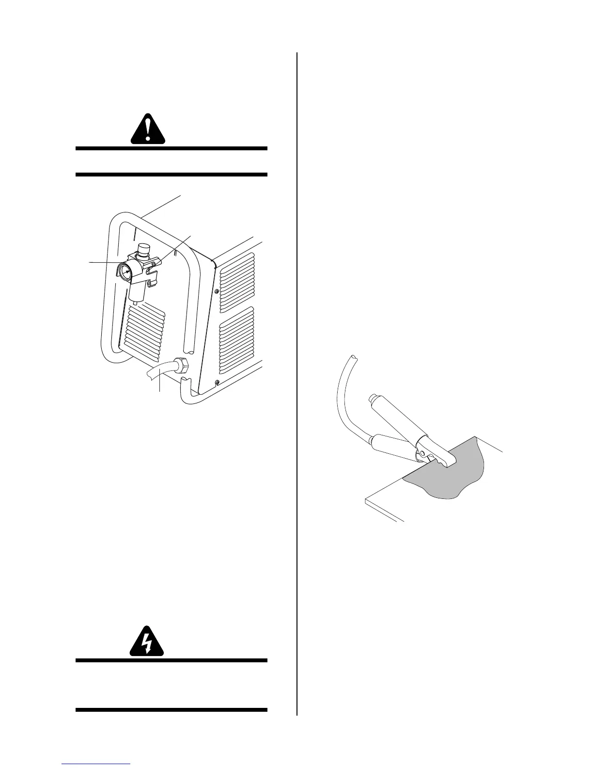
D. Work Cable Connection
Check for a solid work cable connection to the work-
piece.
Make a solid work cable
connection to the work-
piece or cutting table
A-00925
E. Torch Connection
Check that the torch is properly connected.
F. Power On
Place the ON/OFF switch to the ON (up) position.
G. Select Current Output Level
Set the current output level between 20-80 amps for
cutting or gouging.