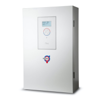
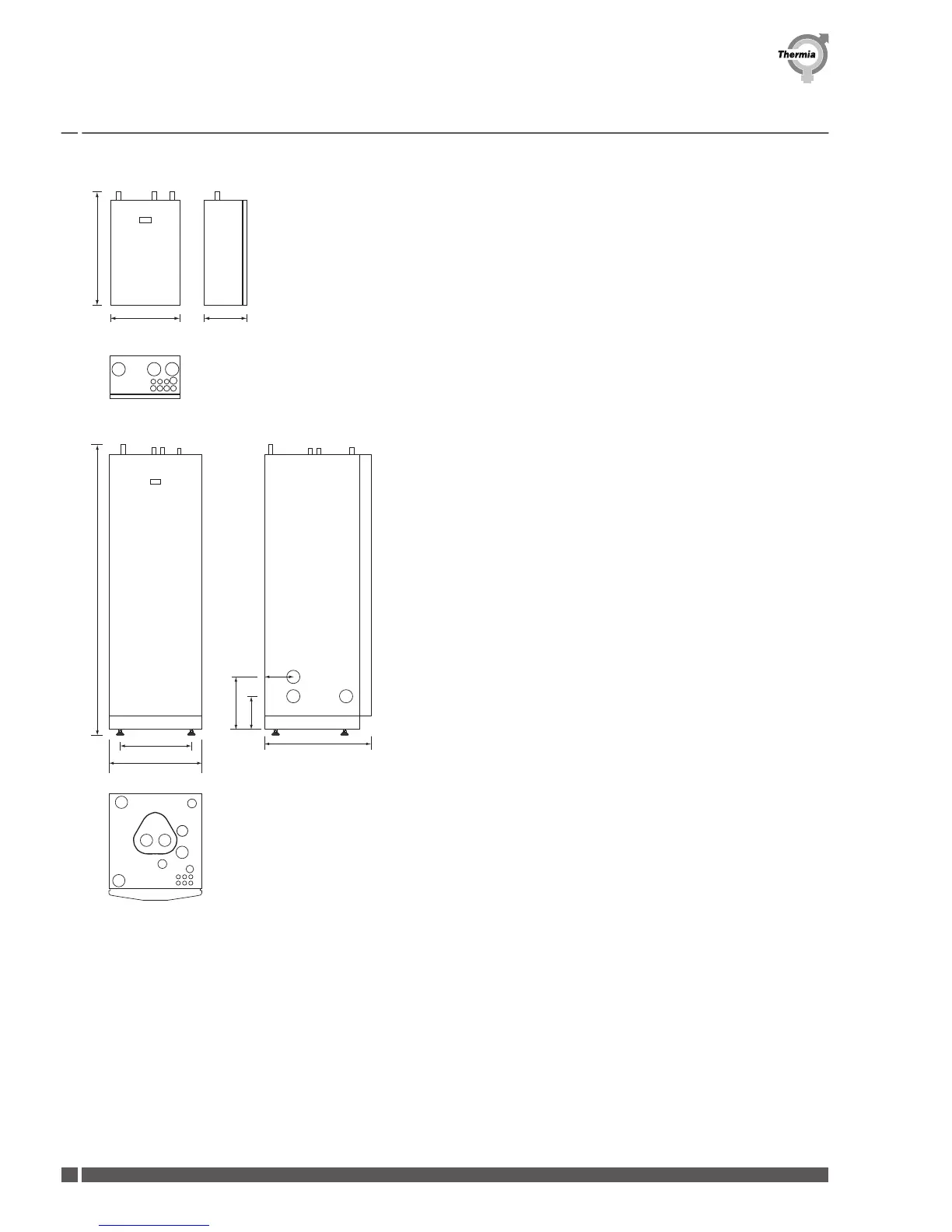
1. Supply line for heating system, 28 mm Cu
2. Supply line to water heater, 28 mm Cu
3. Supply line from heat pump, 28 mm Cu
4. Lead-in for supply, sensor and communication cables
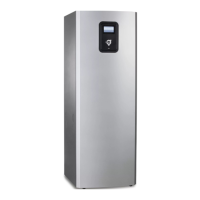
Control unitAtec Total
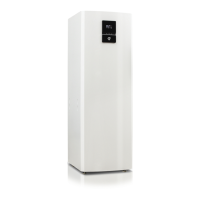
1. Supply line heating system,28 mm Cu
2. Return line heating system,28 mm Cu
3. Connection for bleed valve,22 mm Cu
4. Hot water line,22 mm Cu
5. Cold water line,22 mm Cu
6. Lead-in for supply, sensor and communication cables
7. Supply or return line heat pump
8. Supply or return line heat pump
9. Extra knock-out
10. Safety valve for temperature and pressure (only applies to certain models)
Position 7 and 8 can be connected to either the left or right-hand side or at the
bottom of the control unit.
Installation Guide
Atec
VMBQY102 Thermia Värmepumpar
12
 Loading...