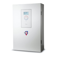
5.2 Control centre
5.2.1 Installation
The control centre contains the necessary components for voltage supply, control systems and operation.
Caution The control centre must be installed in a frost-free environment.
5.2.2 Atec Standard electrical components in the control centre
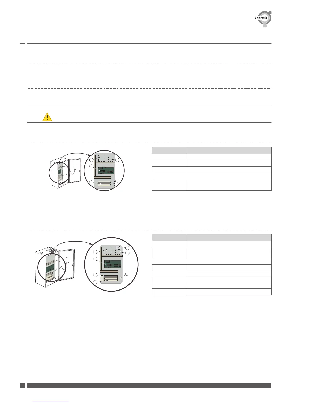
Fig. 1: Control unit
Position Description
1 Terminal block
3 Hub card
4 Space for expansion card (accessory)
5 Space for communications card (accessory)
6 Space for terminal block for expansion card
(accessory)
5.2.3 Atec Plus electrical components in the control centre
Fig. 2: Control unit
Position
Description
1 Terminal block
2 Terminal block for internal electrical auxiliary
heater (IH)
3 Hub card
4 Space for expansion card (accessory)
5 Space for communications card (accessory)
6 Space for terminal block for expansion card
(accessory)
7 Overheating protection
Installation Guide Atec
VMBQY102 Thermia Värmepumpar
24
 Loading...