5 Electrical Installation
Danger Electrical voltage! The terminal blocks are live and can be highly dangerous due to the risk of electric shock.
All power supplies must be isolated before electrical installation is started. The heat pump is connected inter-
nally at the factory, for this reason electrical installation consists mainly of the connection of the power sup-
ply.
Caution Electrical installation may only be carried out by an authorized electrician and must follow applicable local
and national regulations.
Caution The electrical installation must be carried out using permanently routed cables. It must be possible to isolate
the power supply using an all-pole circuit breaker with a minimum contact gap of 3 mm. (The maximum load
for externally connected units is 2A).
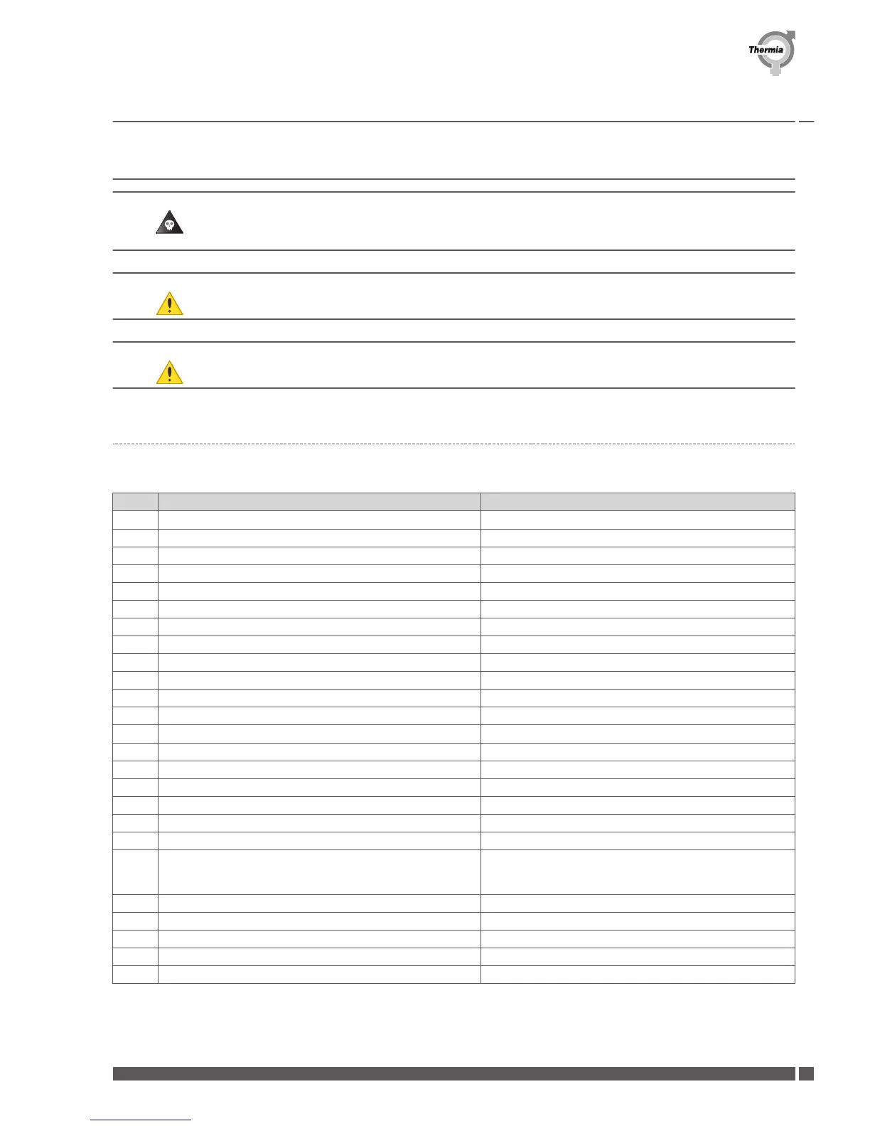
5.1 Electrical connection points
This table shows how different electrical equipment should be connected. The positions in the table refers to the system solutions.
Pos
Description Connect to
5 Heat pump unit
33 Circulation pump (shunt additional heater) 101.2 and N
36 Circulation pump (system) 101.1 and N
40 Control unit
50 Outdoor sensor 305 and Com
51 System supply line sensor
52 Return line sensor
53 Hot water starting sensor
55 Hot water sensor top TWC
60 Sensor pool 208.1 and Com
62 Room sensor DC to 121.1 A to 121.3 Gnd to Gnd B to 121.5
63 Shunt valve (additional heater) +102.3 -102.4 and N
64 Supply line sensor, mixing valve 118.2 and Com
79 Reversing valve cooling tank M3.3 to L1:1 M3.6 to 101.6 M3.2 to N
101 Reversing valve pool M3.3 to L1:1 M3.6 to 201.1 M3.2 to N
107 Shunt valve (distribution circuit 1) +102.5 - 102.6 and N
108 Supply line sensor (distribution circuit 1) 118.3 and Com
109 Circulation pump (distribution circuit 1) 101.3 and N
114 Immersion heater L1, L2 and N
117 Additional heater 101.4 and N 230Vac
Alternative: Pot free relay max in 250V 8A connect in 101.8
out 101.16
120 Fan coil
133 Shunt valve (distribution circuit 2) +202.1 - 202.2 and N
134 Supply line sensor (distribution circuit 2) 208.3 and Com
135 Circulation pump (distribution circuit 2) 201.5 and N
355 Connecting self-regulating heating cable for draining L1.1, PE and N
Installation Guide Atec
Thermia Värmepumpar VMBQY102
23
 Loading...