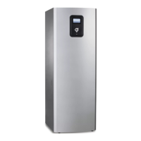
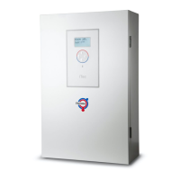
Control unitAtec Total
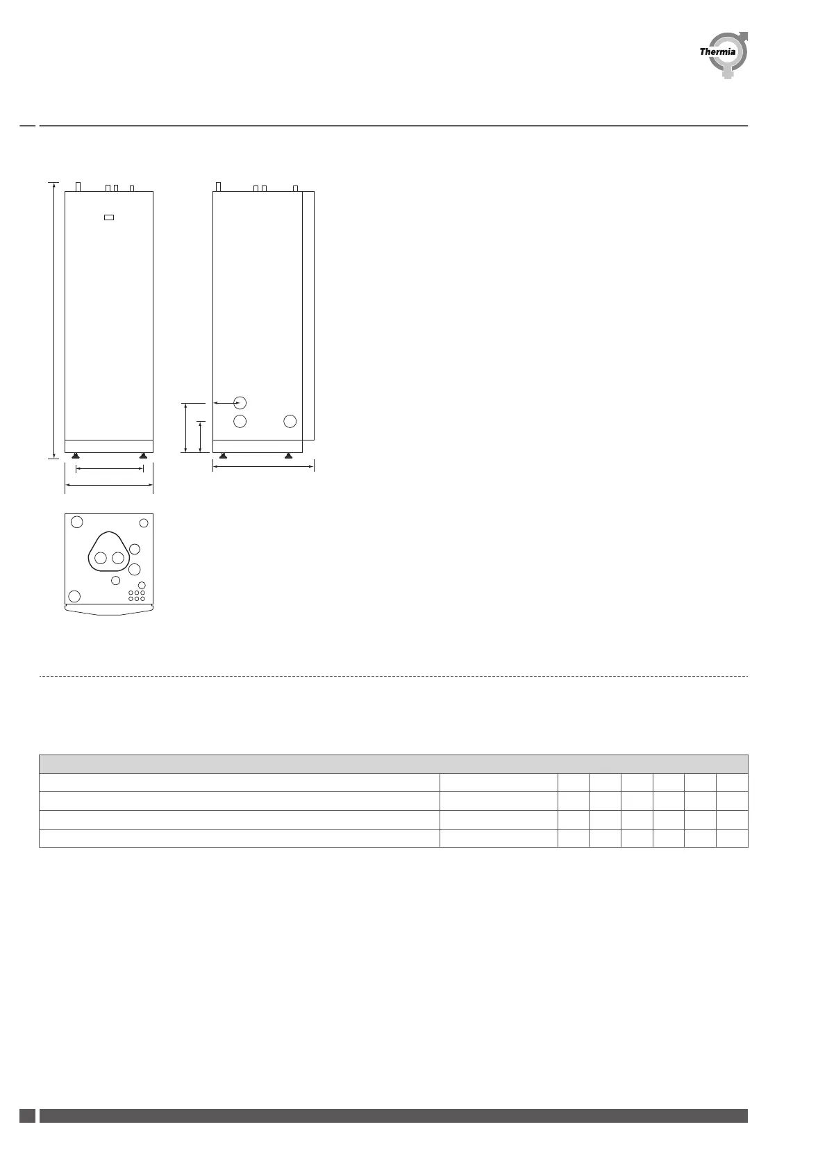
1845 ±10
596
455
690
1
2
3
4
5
125
210
330
6
7
8
9
10
1. Supply line heating system,28 mm Cu
2. Return line heating system,28 mm Cu
3. Connection for bleed valve,22 mm Cu
4. Hot water line,22 mm Cu
5. Cold water line,22 mm Cu
6. Lead-in for supply, sensor and communication cables
7. Supply or return line heat pump
8. Supply or return line heat pump
9. Extra knock-out
10. Safety valve for temperature and pressure (only applies to certain models)
Position 7 and 8 can be connected to either the left or right-hand side or at the
bottom of the control unit.
2.2
Sound levels
The instantaneous sound power in variable speed mode depends on meteorological conditions as well as on present heating demand.
For a heat pump sized according to common practice that operates on/off with 1h or less on cycle periods, the sound level will normally
not exceed the nominal at temperatures A7W30/35.
A weighted Sound Power Level, dB(A) ref. 1 pW
Heat pump size kW 6 9 11 13 16 18
Fan running at constant rpm according to the 'Silent mode' function Sound power, dB(A) 60.1 59.2 59.6 61.0 64.9 72.6
Fan running at the variable speed mode default rpm Sound power, dB(A) 61.3 61.0 61.0 62.4 67.0 76.3
Fan running at the variable speed mode maximum rpm Sound power, dB(A) 66.4 65.8 64.6 66.6 71.1 81.0
Tab. 1: Sound power levels according to ISO EN 3741 at A7W30/35
Planning guide
Atec
VIIFB102 Thermia Värmepumpar
10
 Loading...