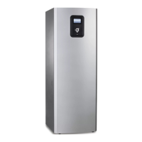
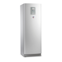
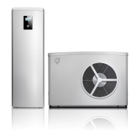
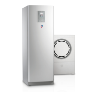
3 System example
3.1 System example Atec Total
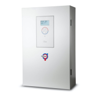
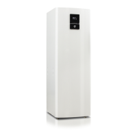
Atec Total includes the control module with supply and return pipe sensors, circulation pump, 3-way valve, electric auxiliary heater and
water heater. The heat pump produces heat, cooling and hot water.
Production of heating and hot water cannot occur at the same time because the exchange valve for heating and hot water is positioned
after the heat pump and the auxiliary heater. Hot water production is prioritised ahead of heat and cooling. Two heating circuits can be
connected, one using a shunt. The shunt is controlled by the heat pump control system.
The flow line temperature is controlled with reference to the outside temperature following a set heat curve. The additional heater starts
automatically on demand. The auxiliary heater carries out peak heating charging (anti-legionella function) in those operating modes
that permit auxiliary heat.
Buffer tank is installed for equalisation of the temperature for the heating system and to guarantee sufficient energy when defrosting.
The buffer tank volume must be 10 l/kW heat pump output (for systems with water heaters).
For position explanations, see the chapter Symbol Key.
Planning guide
Atec
Thermia Värmepumpar VIIFB102
11
 Loading...