transferring heat to the refrigerant circuit, which is then given off in
the air heat exchanger.
If the hot water heater is installed the control unit will alternate
between cooling and hot water production with prioritisation for the
hot water requirement.
3.1.7 Speed controlled fan
The fan starts at a nominal speed, which differs depending on the size
of output. The fan speed is adjusted up or down as required which is
determined by the temperatures in the refrigerant circuit.
3.1.8 Electronic expansion valve
When the refrigerant passes the expansion valve the pressure and
temperature of the refrigerant are reduced. In this way the energy in
the outdoor air is available to the refrigerant circuit. By regulating the
opening degree of the expansion valve one can optimise the flow in
the refrigerant circuit in different operating conditions. Control of the
electronic expansion valve is based on the measurements of tempera‐
tures and pressures in the refrigerant circuit and outside air.
3.1.9 Auxiliary heat
The auxiliary heater is included in Atec Plus and Atec Total and is
available as an accessory for Atec Standard. An auxiliary heater con‐
sists of an immersion heater, which is located on the supply pipe
ahead of the reversing valve.
If the auxiliary heater is installed it engages AUTO mode automatically
when the heat demand is greater than the heat pump’s capacity.
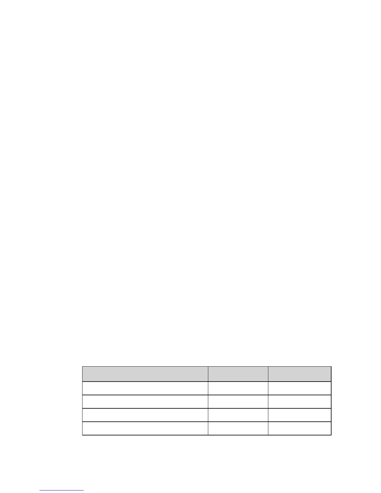
Immersion heaters in Atec series intended for 400V voltage supply
have three heating elements (AUX. HEAT 1, 2 and 3) and can be con‐
trolled in five power stages. Products for 230V have two heating ele‐
ments (AUX. HEAT 1 and 2) and are controlled in three power stages.
The two stages 4 and 5 cannot be engaged when the compressor is in
operation as opposed to stages +4 and +5 where it is possible.
230V
400V
Step 1 3 3
Step 2 6 6
Step 3 9 9
Step 4 12
10 – User manual 086L0130 Rev. 1 EN
 Loading...