The set point value for the supply line and the
max value of the return line is shown within
brackets The max value indicates the tempera‐
ture at which the compressor is stopped. No val‐
ues can be changed in this menu.
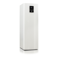
The different temperatures that the installation has are shown here. All
temperatures are stored back in time so that they can also be dis‐
played in the form of graphs.
If ROOM shows 20°C the heat curve is unaffected. If ROOM shows
higher or lower, this indicates that the heat curve has been adjusted
up or down.
5.7 Reading the operating time
COMPRESSOR shows the total time in hours that the heat pump has
been in operation since installation.
AUX. HEAT 1, 2 and 3 refer to the immersion heater and its different
power stages.
5.8 Manual defrost, outdoor unit
If the heat pump requires defrosting you can run a defrosting proce‐
dure manually from the control computer.
To defrost manually:
User manual 086L0130 Rev. 1 EN – 21
 Loading...