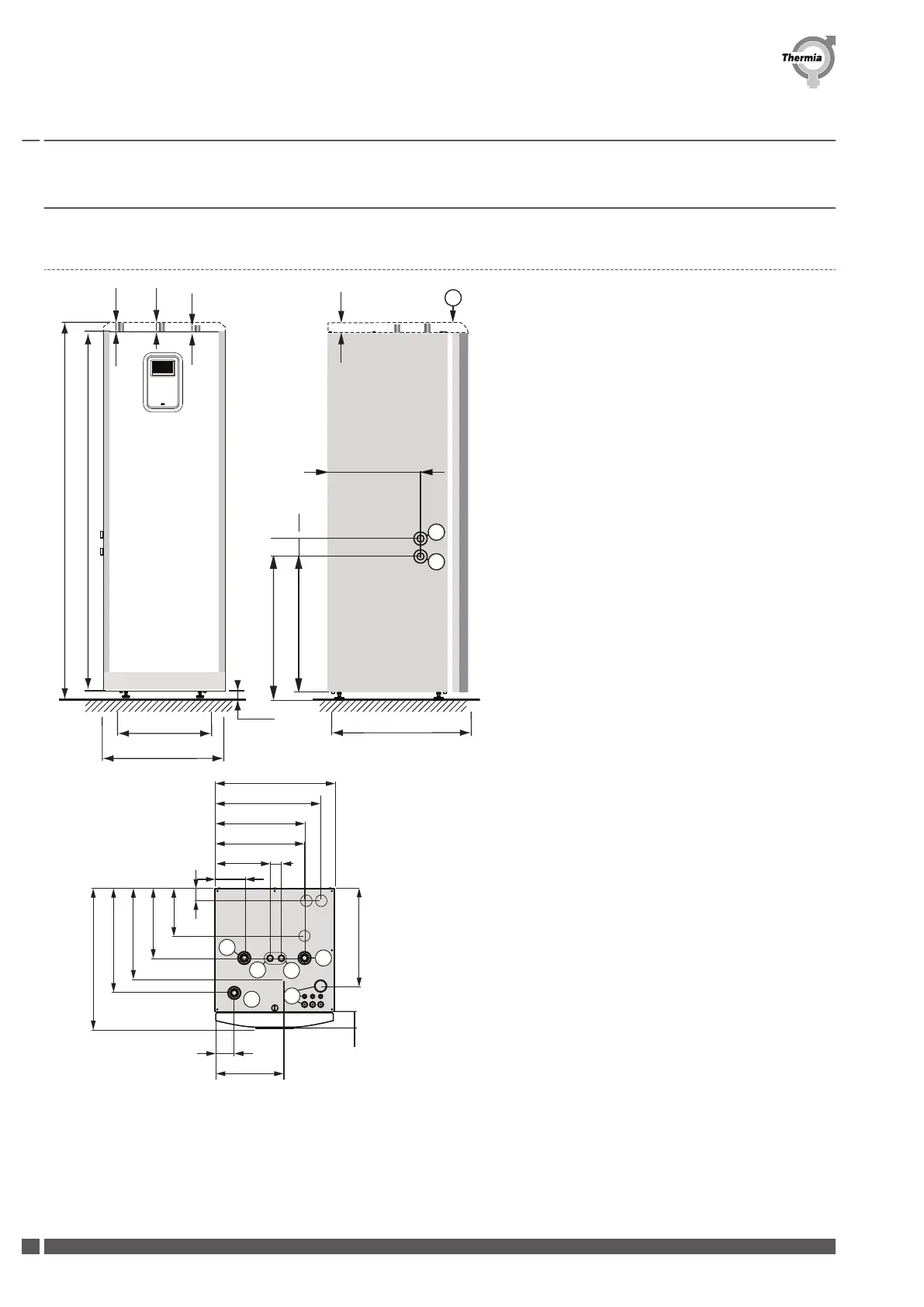
2 Heat pump data, dimensions and connections
2.1 Atlas and Calibra
1864 (±10)
1770
455
598
703
40 ±10
686
726
75
498
272
55
85
3
5
1
9
2
8
4
600
526
449
445
148
240
350
455
523
710
64
93
343
493
6
7
48
49
40
53
1 Brine in, 28 mm (left or right)
2
Brine out, 28 mm (left or right)
3 Heating system supply pipe, 28 mm
4 Heating system return pipe, 28 mm
5 Connection for bleed valve, 28 mm
6 Hot water line, 22 mm
7 Cold water line, 22 mm
8 Lead-in for supply, sensor and communication ca-
bles
9 Top hood, Atlas (accessory for Calibra)
The brine lines (1) and (2) can be connected on either the
left or right-hand sides or to the two knock out holes on
the top.
Installation Guide Atlas & Calibra
BWCA01IG0202 Thermia AB
8
 Loading...