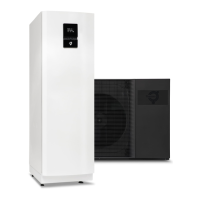
Parameter Meaning
TANK TOP UP Activate high temperature mode when the external auxiliary heater is selected.
The external auxiliary heater will heat the tank to the highest permitted tank temperature.
Factory setting: , range: – ON
RED. TANK TEMP The function permits a reduction of the temperature in the tank when the temperature reduction is set to active
in the CALENDAR menu.
The temperature that is set in the tank is calculated by the system when the function has been activated.
The function is only active at CONFIGURATION = TANK CONTROL and all configured circuits are set to shunt at
constant temperatures.
Factory setting: , range: – ON
7.8 OP. DATA
Parameter Meaning
HEAT DEMAND/
COOL DEMAND/
POOL DEMAND
Shows the heating, cooling or pool heating demand for the system and is used for controlling the supply line
temperature.
H.C INTEGRAL Heat circuit integral value. Representation of the building heat demand. This is only shown in buffer tank config-
urations.
OUTDOOR Shows the temperature on the outdoor sensor.
ROOM Shows the temperature on the room sensor.
HOT WATER Displays the temperature on the hot water sensor on the condition that hot water production is permitted.
SUPPLY LINE Shows the temperature on the supply line sensor.
The calculated supply temperature to the heating system group is within brackets.
CONDENSER OUT Shows the temperature on the condenser out sensor.
CONDENSER IN Shows the temperature on the condenser in sensor.
The stop temperature, MAX RETURN is within brackets.
SYSTEM SUPPLY Displays the temperature of the system supply line sensor at the buffer tank system or if the external auxiliary
heater is activated.
DISTR.CIR.1 Shows the temperature on the distribution circuit 1 sensor (liquid line).
The calculated supply temperature is within brackets.
DISTR.CIR.2 Shows the temperature on the distribution circuit 2 sensor (evaporating temperature).
The calculated supply temperature is within brackets.
BUFFER TANK Shows the temperature on the sensor for the buffer tank.
REFR 1 Shows the temperature at refrigerant sensor 1.
REFR 2 Shows the temperature at refrigerant sensor 2.
POOL Displays the temperature on the pool sensor on the condition that pool operation is permitted.
CURRENT Displays the current consumption in Amperes. The set value for MAX CURRENT is shown in brackets.
Only appears if CURRENT LIMITER is selected in the Service menu.
DISCH. PIPE Shows the temperature at the discharge pipe sensor.
COMPR. TEMP Shows the temperature of the compressor.
AMB.T.OUTD.UNIT Shows the ambient temperature of the outdoor unit.
7.9 OPERAT. TIME
Parameter Meaning
COMPRESSOR Operating time for compressor.
HEATING Operating time for heating.
COOLING Operating time for cooling.
HOT WATER Operating time for hot water with compressor.
IMM. HEAT 1 Operating time for IMMERSION HEATER 1.
Commissioning iTec XT
Thermia AB AWIXT01CG0102
33