Engine Maintenance
102
4. Use the Mechanics/Premium HMI Control
Panel to enter the Interface Board Test Mode.
Refer to the appropriate Microprocessor
Diagnostic Manual for specific information
about the Relay Test Mode.
5. Energize the fuel solenoid by energizing the
run relay with the Interface Board Test Mode.
NOTE: The fuel solenoid must be energized
when it is installed. If not, the plunger and
the linkage may not line up correctly and the
fuel solenoid will not function properly.
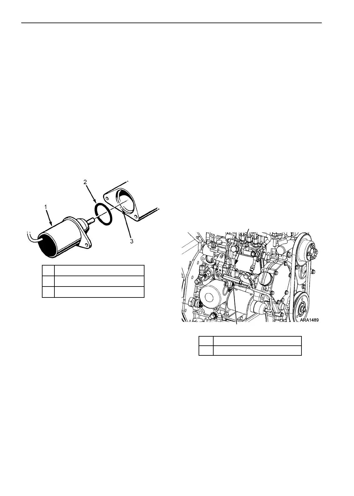
6. Place the O-ring in the groove in the end of
the fuel injection pump. Make sure that the
O-ring is positioned correctly during
installation to avoid damage and leaks.
7. Install the new fuel solenoid.
8. Press the
OFF key to turn the unit off after
installing the fuel solenoid.
Engine Speed Adjustments
When the diesel engine fails to maintain the
correct engine speed, check the following before
adjusting the speed:
1. Check the electric fuel pump filter. Recheck
the speed.
2. Check the operation of the electric fuel pump.
3. Bleed the air out of the fuel system. Recheck
the speed.
Make the engine speed adjustments with the
engine fully warmed up.
Low Speed Adjustment
1. Start the unit and let it run until the engine is
warmed up.
2. Adjust the setpoint to make the engine run in
low speed (or use Service Test Mode LSC)
and check the engine speed. See
“Specifications” for the correct low speed.
3. If the engine speed is not correct, loosen the
jam nut on the low speed adjustment screw.
4. Turn the low speed adjustment screw to
change the engine speed. Turn the screw in to
increase the engine speed. Turn the screw out
to decrease the engine speed.
5. Set the engine speed at the correct low speed,
and tighten the jam nut
6. Recheck the engine speed.
High Speed Adjustment
1. Start the unit and let it run until the engine is
warmed up.
2. Adjust the setpoint to make the engine run in
high speed (or use Service Test Mode HSC)
and check the engine speed. See
“Specifications” for the correct high speed.
1. Fuel Solenoid
2. O-ring
3. Groove in Fuel Injection Pump
Figure 182: Fuel Solenoid Components
1. Low Speed Adjustment Screw
2. High Speed Adjuster
Figure 183: Engine Speed Adjustments

 Loading...