Electrical Maintenance
39
Manual Defrost Switch
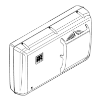
A manual defrost switch is located in the In-Cab
control box. Pressing the manual defrost switch
initiates the defrost cycle if the defrost termination
switch is closed and the unit is in cool mode.
Defrost Termination Switch
The switch is mounted in the evaporator coil and
controls the defrost cycle in response to the
evaporator coil temperature. The switch is closed
when the evaporator coil temperature is below 36
F (2.2 C). completing the defrost circuit to ground
and preparing the electrical system for the defrost
cycle.
When the unit does shift into a defrost cycle, the
evaporator fan stops, and heat from the hot
refrigerant gas melts the frost from the evaporator
coil. The switch opens and terminates the defrost
cycle when the evaporator coil temperature rises
above 48 F (8.9 C).
Defrost Relay
The defrost relay controls operation of the defrost
cycle. When the defrost timer or the manual
defrost switch completes the circuit through the
defrost termination switch to ground, the defrost
relay is energized. This energizes the defrost
solenoid valve (wire 26) and de-energizes the fan
relay.
The defrost relay stays energized until the defrost
cycle is terminated by the defrost termination
switch or the ON-OFF Key is pressed.
Defrost Solenoid Valve
The defrost solenoid valve is an electrical valve
that controls the flow of refrigerant through the
refrigeration system.
The defrost solenoid valve is energized by the 26
wire (Pin 1 C-1). When the defrost solenoid valve
is energized it routes hot refrigerant gas to the
evaporator.
Testing The Defrost System
To test the defrost system, run the unit on cool
until the evaporator coil temperature is below
36.0 ± 5.4 F (2.2 ± 3.0 C) and press the manual
defrost switch.
If the unit doesn’t shift to defrost cycle go to step
1.
1. Check the evaporator temperature.
Be sure the evaporator temperature is actually
below 36.0 ± 5.4 F (2.2 ± 3.0 C), otherwise
the unit will not defrost. Use a test
thermometer to check the evaporator
temperature.
2. Check the defrost termination switch.
If the unit fails to defrost, place a jumper wire
between the 12 and CH wires at the defrost
termination switch. Press the manual defrost
switch.
If the unit shifts to defrost, the defrost
termination switch is defective.
If the unit does not shift to defrost, check for
an open circuit in the 12 wire back to Pin 2
C-3. If the 12 wire is not open go to step 3.
3. Check voltage on Pin 1 C-3.
If voltage is present on Pin 1 C-3, replace the
defrost relay.
If voltage is not present, go to step 4.
4. Check for open circuit on wire GR that goes to
the In-Cab control box (Pin 8 C-9).
If the wire GR is not open, go to step 5.
5. Press and hold manual defrost switch, check
the voltage on Pin 8 C-9.
If voltage is present on Pin 8 C-9 and the rest
of the above mentioned points are correct,
replace the printed circuit board.
If voltage is not present on Pin 8 C-9, check
the In-Cab control box.
Defrost Timer Test
The defrost timer initiates the defrost cycle.
1. Verify that the evaporator coil temperature is
lower than 36.0 ± 5.4 F (2.2 ± 3.0 C). If not,
place a jumper wire between the 12 and CH
wires at the defrost termination switch.
2. Set the defrost timer to approximately 1
minute (selector switches A:
↓, B:↓ and round
red selector in position 4).

 Loading...


