24
APPLICATION OVERVIEW
Control and monitoring systems can play an essential
role in heat tracing applications which range from
freeze protecting water lines to maintaining elevated
process temperatures. While mechanical thermostats
have been used successfully for many heat tracing
applications, a more complete control and monitoring
solution can be necessary for critical heat tracing
applications. Advancements in technology have made
electronic control and monitoring units both cost
effective and more reliable. These systems conserve
energy, extend system life, and ensure accurate
temperatures are maintained, for reduced operating
cost and increased plant reliability.
The Genesis Controller's key features include:
• Monitor electric heat trace circuit load currents
• Selectable control methods (On/Off, On/Off with Soft
Start, Proportional, Ambient Proportional) for each
individual circuit
• Programmable alarm set points, with time delay and
remote alarm acknowledgment and reset capabilities
• Programmable "trip" set-points for each circuit
• Temperature sensor status indication
• Unique circuit identifi er (48 characters maximum)
• Communication to host computer via Ethernet
communications
• Adjustable ground/earth leakage "trip" and/or alarm
capabilities
• Addressable RTD Temperature Sensors - up to twenty
(20) per circuit
• Up to 6 months history to aid in troubleshooting
• ISO drawing in png format for viewing on Genesis HMI
* Additional cabinet types are available. Contact Thermon for details.
** Rating based on extended heat sinks. Multiple single pole relays may
be used for two and three phase circuits. Higher voltage rated relays
are also available as an option.
GENESIS CONTROLLER COMPONENT
APPROVALS
Genesis Controller components are certifi ed for
nonhazardous locations, hazardous locations, and Purge
for hazardous locations
IEC/EN/UL/CSA 61010-1
Ex ec IIC T4 Gc; II 3 Ex ec IIC T4 Gc
Class I, Division 2, Groups ABCD T4; Class I, Zone 2 Group IIC T4
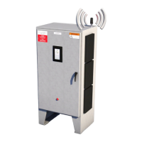
GENESIS CONTROLLER
CONTROL AND MONITORING SYSTEM
GENESIS CONTROLLER
SYSTEM SPECIFICATIONS (Based on lowest rating of all
components)
Environmental:
Hazardous and Ordinary Locations
• Indoor and Outdoor-Solid State Relays
Ordinary Locations
• Indoor and Outdoor- Power Distribution and
Mechanical
Relays
Operating Ambient Range: -40°C (-40°F) to 60°C (140°F)
Enclosures: Type 4X, IP 66 *
Controller Supply Voltage: 100-240 Vac, 50/60 Hz
Heat Tracing Voltages: 100-600 Vac
User Interface: 231 mm x 139 mm (10.6’’ x 5.5”) LVDS TFT
LCD glove touch panel
Maximum Number of Circuits: Seventy-two (72)
Temperature Sensors per Circuit: Up to twenty (20) 100
Ω Platinum, 3 wire RTD's
Current Switching Device Options:
Solid State Relay **
1-pole
2-pole
Mechanical Relay:
Per design requirements
Control Methods:
Process Sensing:
On/Off, On/Off Soft Start, Proportional
Ambient Sensing:
Proportional, Ambient Proportional -Mechanical
(APCM), APC
Control Temperature Range: -129°C (-200°F) to 600°C
(1112°F)
Alarm Settings:
Low, High Temperature, and High Temperature Trip
Low, High Current, and High Current Trip
High Ground/Earth Leakage Current
RTD and Relay Faults
Loss of Communication
Programming Error
Trip Settings:
High Temperature, Heater Current, Ground or Earth
Leakage
Current
Networking Communications:
External: Ethernet
External Alarm Relays:
Up to seven mechanical, 6 A @ 250 Vac or Vdc
Nonhazardous Locations
ETL Listed Conforms to: UL STD. 508A
Certifi ed to: CSA STD. C22.2 NO. 14
GENESIS CONTROLLER SYSTEM APPROVALS
Hazardous Locations (Purge)
ETL Listed Conforms to: UL STD. 508A. NFPA STD. 496
Certifi ed to: CSA STD. C22.2 NO. 14
Hazardous Locations
ETL Listed Conforms to: UL STD. 508A. UL STD. 12.12.01
Certifi ed to: CSA STD. C22.2 NO. 14. CSA STD. C22.2 NO. 213