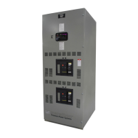
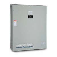
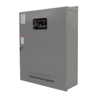
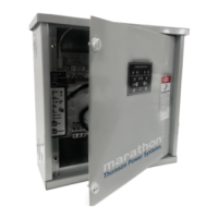
TS 880 TRANSFER SWITCH
PM064 REV8 10/01/25 4 Thomson Technology
q Change voltage taps of the potential transformers (i.e. PT’s) to system voltage (refer to
drawings)
q Once the voltage taps have been set to correct operating voltage, the “control circuit
isolation plug” on the mechanism, may be reconnected, prior to voltage energization.
q Change TSC 800 programming (refer to the TSC 800 instruction manual (PM049). The
following settings will require reprogramming:
Ø System voltage
Ø Utility under voltage pickup (typically 90% of system voltage)
Ø Utility under voltage dropout (typically 80% of system voltage)
Ø Utility over voltage pickup (typically 110% of system voltage)
Ø Utility over voltage dropout (typically 105% of system voltage)
Ø Generator under voltage pickup (typically 90% of system voltage)
Ø Generator under voltage dropout (typically 80% of system voltage)
Ø Generator over voltage pickup (typically110% of system voltage)
Ø Generator over voltage dropout (typically 105% of system voltage)
Record any changed setting on the TSC 800 Programming Data Sheets for future
reference.
q Complete the blank calibration label and attach to the inside of the transfer switch
enclosure door.
3.4. SYSTEM PHASING-HIGH LEG DELTA SYSTEMS
For systems using high leg delta 240V 3 phase 4 wire systems, connection of supply
conductors must have the correct phasing as shown below.
WARNING!
Failure to match correct system
phasing will result in serious damage
to the TSC 800 controller.