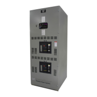
TS 880 TRANSFER SWITCH
PM064 REV8 10/01/25 26 Thomson Technology
q DO NOT perform dielectric tests on the equipment with the control components
in the circuit.
q Check if control components are tight in sockets.
q Periodically inspect all terminals (load, line and control) for tightness. Re-torque
all bolts, nuts and other hardware. Clean or replace any contact surfaces, which
are dirty, corroded or pitted.
q Transfer switches should be in a clean, dry and moderately warm location. If
signs of moisture are present, dry and clean transfer switch. If there is corrosion,
try to clean it off. If cleaning is unsuitable, replace the corroded parts. Should
dust and/or debris gather on the transfer switch, brush, vacuum, or wipe clean.
DO NOT blow dirt into power switching devices.
q Test the transfer switch operation. While the unit is exercising, check for
freedom of movement, hidden dirt, corrosion or any excessive wear on the
mechanical operating parts. Ensure that the power switching device travel is
correct.
Ø Verify all program settings on the TSC 800 controller are as per the
programming sheet supplied with the transfer switch.
Ø Confirm that the yoke operates freely on the yoke pivot bushings. Should
lubrication be required, apply medium weight (SAE 20) oil sparingly at these
points.
Ø The motor and gearbox are permanently lubricated, and should not require
attention under normal operating circumstances.
7.2. SERVICING– 400A-1200A MOLDED CASE TYPE TRANSFER
MECHANISMS
7.2.1. GENERAL DESCRIPTION
The transfer mechanism consists primarily of the transfer motor, a hub assembly,
two operating rods and two power switching device operating yokes.
The reversible transfer motor drives the hub assembly, which in turn moves the
operating rods that are connected to the power switching device operating yokes.
The power switching device toggles are set inside the yokes and are operated by
the yoke. There are two limit switches, which are contacted by the operating yokes
(one for each direction of travel), which disconnect the transfer motor power supply
when the power switching devices have attained full travel. The adjuster screws