APPENDIX “A”
SVF036.DOC 04/12/13 REV 1 THOMSON TECHNOLOGY
©
9087A - 198
th
Street, Langley, B.C. Canada V1M 3B1 • Telephone (604) 888-0110 • Telefax (604) 888-3370
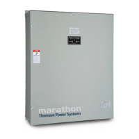
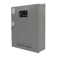
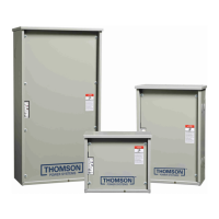
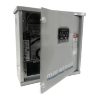
TYPICAL AUTOMATIC TRANSFER SWITCH
COMMISSIONING PROCEDURES
Model Series TS 880
Note: The following commissioning procedures are provided for general information only pertaining to typical site installations
and applications. Contact Thomson Technology for further information as may be required.
DANGER!!!!
Arc Flash and Shock Hazard. Will cause severe injury or death.
Do not open equipment until ALL power sources are disconnected
This equipment must be installed and serviced only by qualified electrical
personnel utilizing safe work practices and appropriate Personal Protective
Equipment (PPE). Failure to do so may cause personal injury or death
CAUTION
Commissioning procedures must be performed by qualified personnel only. Ensure the Automatic Transfer Switch (ATS)
Isolation Plug is pulled prior to energizing the supply sources. Manually place the transfer switch mechanism in the neutral
position prior to applying power. Failure to do so may result in equipment failure or personal injury.
Pre-Commissioning Checks Prior to Commissioning Agent On-Site (to allow loads to be
supplied prior to final commissioning)
1) Verify supply source voltage to be applied to the transfer switch is of the correct nominal value. Confirm this to be the
same as listed on the ATS drawings and the ATS equipment label. For other system voltages refer to the ATS instruction
manual for re-configuring procedures prior to energization. FAILURE TO RE-CONFIGURE ATS VOLTAGE TO MATCH
SYSTEM VOLTAGE WILL RESULT IN EQUIPMENT MALFUNCTION AND DAMAGE.
If ATS voltage is changed, record the new voltage on the TSC 800 Component Calibration Label.
2) For 240V High Leg Delta systems refer to the ATS instruction manual for correct phasing required and re-configuring
procedures. FAILURE TO OBTAIN THE CORRECT ATS PHASING WILL RESULT IN EQUIPMENT MALFUNCTION AND
DAMAGE.
3) Confirm cable size is correct for the lugs supplied in the transfer switch (line and load). Confirm the cables were meggered
by the electrical contractor to ensure no cross phase connections or conduction to ground.
4) Confirm cable lugs are properly torqued. Confirm cable installation; ensure the cables do not interfere with normal
equipment operation or which may cause component damage.
5) Manually operate the transfer mechanism by opening or closing the utility or generator power switching device to the
appropriate source of supply. Leave the Isolation Plug disconnected until final Transfer Switch Commissioning is to be
completed.
Final Commissioning
1) Verify installation of the Automatic Transfer Switch as per installation manual and verify wiring (also see the Pre-
Commissioning Checks). Confirm phase, neutral and grounding conductors are installed as per electrical code
requirements. Note: Confirm neutral conductors of both sources are correctly installed and are solidly grounded for 3 phase
4 wire configurations.
2) Check for mechanical damage (shipping or installer).
3) Check for cable interference with mechanical moving parts or the motor brake on 100A-250A ATS mechanism.